Compact drain-cleaning device with hair-snagging pad

a compact, drain-cleaning technology, applied in water installations, cleaning processes and apparatus, construction, etc., can solve the problems of clogging the drainpipe connected to sinks, bathtubs and showers, objects falling down the drain accidentally, and no device is suitable for safe and inexpensive use, so as to achieve the effect of effective hair-snagging ability and safer for users

Active Publication Date: 2006-02-02
IMAGINATION PROD CORP
View PDF13 Cites 9 Cited by
  • Summary
  • Abstract
  • Description
  • Claims
  • Application Information

AI Technical Summary

Benefits of technology

[0012] There has thus been outlined, rather broadly, the more important features of the invention in order that the detailed description thereof that follows may be better understood, and in order that the present contribution to the art may be better appreciated. There are additional features of the invention that will be described hereinafter and which will form the subject matter of the claims appended hereto.
[0013] In this respect, before explaining at least one embodiment of the invention in detail, it is to be understood that the invention is not limited in its application to the details of construction and to the arrangements of the components set forth in the following description or illustrated in the drawings. The invention is capable of other embodiments and of being practiced and carried out in various ways. Also, it is to be understood that the phraseology and terminology employed herein are for the purpose of description and should not be regarded as limiting.
[0014] As such, those skilled in the art will appreciate that the conception, upon which this disclosure is based, may readily be utilized as a basis for the designing of other structures, methods and systems for carrying out the several purposes of the present invention. It is important, therefore, that the claims be regarded as including such equivalent constructions insofar as they do not depart from the spirit and scope of the present invention.
[0015] Further, the purpose of the foregoing abstract is to enable the U.S. Patent and Trademark Office and the public generally, and especially those skilled in the art who are not familiar with patent or legal terms or phraseology, to determine quickly from a cursory inspection the nature and essence of the technical disclosure of the application. The abstract is neither intended to define the invention of the application, which is measured by the claims, nor is it intended to be limiting as to the scope of the invention in any way.
[0027] (k) Another object of the invention is to provide a device for removing hair and fibrous clogs that has effective hair-snagging ability without using metal hooks which tend to get snagged onto the drain pop-up apparatus within the drain when attempting to maneuver the device to snag hair clogs. Also, by utilizing polymeric hook and loop type material, the present invention is safer for the user than wire hook devices.
[0028] Further objects and advantages of the present invention will become apparent from a consideration of the drawings and ensuing description.

Problems solved by technology

None however fulfill the need for a safe and inexpensive device that is compact and effective in retrieving hair clogs from the upper portions of drainpipes found in the average home which are connected to sinks, tubs and showers.
A common problem that plagues people that use modern plumbing is the inevitable development of clogs that develop in the drainpipes connected to sinks, bathtubs and showers.
These clogs may result from objects accidentally being dropped down a drain, but more typically are the result of a build-up of the soaps, oils, greases, hair and other organic material that is washed down the drain.
These devices are often effective in freeing clogged drains but don't offer a consistent solution to opening clogged drains that are largely a result of an accumulation of hair that typically occurs in the trap and especially hair that becomes entangled in the drain pop-up lever arm assembly just below the drain pop-up in the opening of the drain.
Each device of the current art is seen to be deficient in providing a solution for these upper-drain hair clogs upon examination.
Plungers that utilize air or water pressure to dislodge clogs in drains don't reliably dislodge hair clogs because the pressurized air or water force is not great enough to break hair away from solid, fixed protrusions within the drainpipe.
These however have the drawbacks of being large and unwieldy for the average homeowner and often cannot be used for upper-drain clogs or those occurring from the drain opening to the trap because the drain opening around the peripheral area of the drain pop-up of a sink is not large enough to accommodate the metal spiral end of the snake.
Smaller spiral-tipped sink snakes are available but still very unwieldy and not adept at snagging hair entangled around the drain pop-up lever arm.
In addition, most of these devices are metal and subject to rust and corrosion.
They are either unsafe for the user because of sharp edges, or have wire hooks which can get hooked on the pop-up lever arm, or they are not compact making them inconvenient to store or transport.
These devices usually have length and cannot be coiled in a stationary fashion, which means a homeowner cannot store them in a drawer or the artisan cannot transport then in a toolbox due to their length.
This is also a disadvantage in commercial sale since these devices cannot readily be packaged with the shelf size drain products that they work hand-in-hand with to provide a complete drain cleaning solution.
These are often effective in chemically “burning away” drain clogs but have the disadvantages of being dangerous to people, pets and the environment.
These chemicals are responsible for a multitude of human poisonings annually as well as eye, lung and flesh injuries from their use and existence in the household.
Consequently the large, cumulative volume that enter our sewage systems represent a hazard to the environment as the chemicals are not readily broken down in sewage treatment plants and flow out into the environment adding unwanted and detrimental pollutants.
In addition, the chemical solutions often flow by hair clogs that are wrapped around the drain pop-up lever arm and are suspended in the center of the drainpipe where the liquids can't effectively work on them.
Unfortunately one drawback of biological products is that they are less effective for rapid treatment of hair-clogged drains.
By not being able to readily free slow flowing drains due to hair clogs, biological drain products are less popular in the marketplace and consequently consumers more frequently purchase the dangerous and harmful chemical products to open drains to the detriment of society in general.
That device is not compact and is limited in the number of hooking elements presented to the clog since they are arranged radially around the elongate shaft which itself is limited in diameter to fit the largest circular dimension of the pie-shaped opening of the drain around the peripheral area of the drain pop-up stopper.

Method used


Image

  • Compact drain-cleaning device with hair-snagging pad
  • Compact drain-cleaning device with hair-snagging pad
  • Compact drain-cleaning device with hair-snagging pad

Examples


embodiment — fig

Preferred Embodiment—FIG. 1A

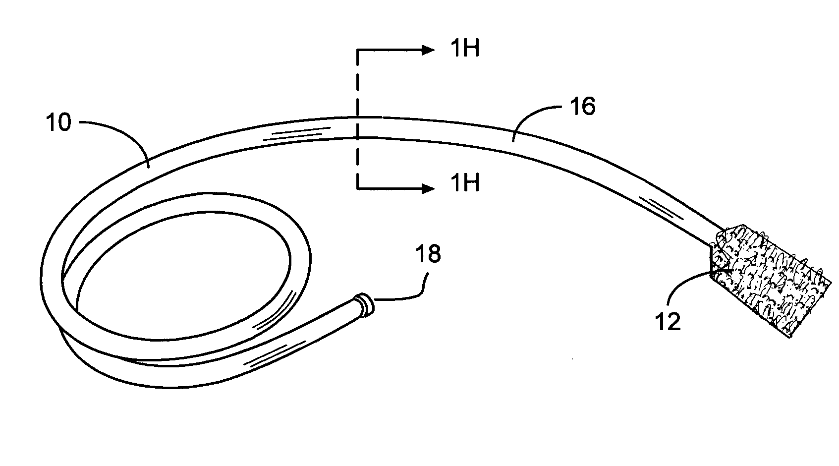
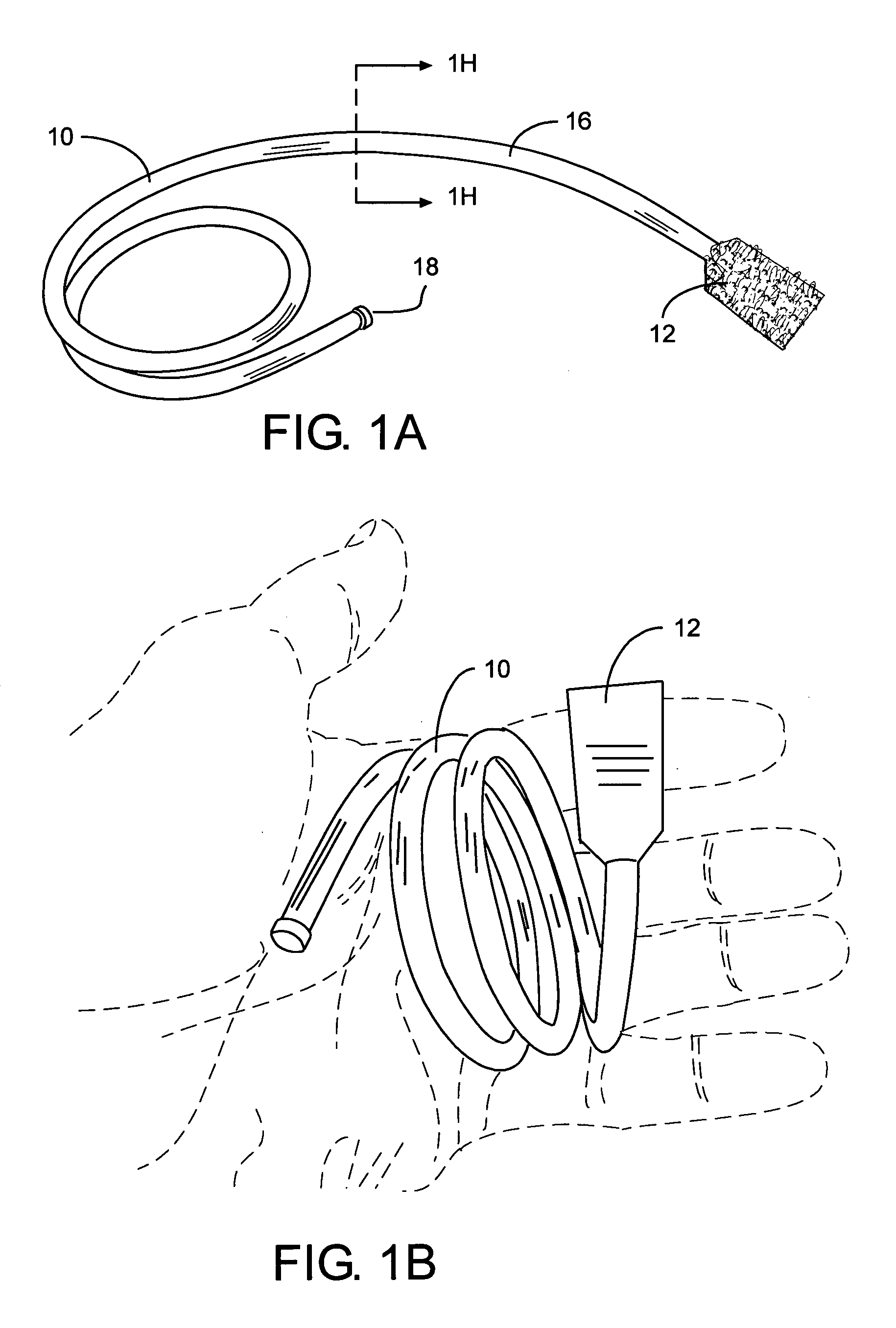
[0051]FIG. 1A shows a perspective view of the preferred embodiment of the invention. The shaft 10 of the device consists of a plastic sheath 16 made from common 3 / 16″ OD PVC plastic tubing with a 90 Shore A durometer hardness with a #16 galvanized wire 14 inserted inside. FIG. 1H is a sectional view of the shaft 10 perpendicular to the longitudinal axis of the shaft 10. The shaft 10 may be of any length but in the preferred embodiment is approximately 61 cm or 24 inches to reach past the typical drain trap. The wire 14 is sealed inside the sheath 16 with a readily available plastic, barbed plug 18 in FIG. 1J that is inserted into the grasping, proximal end of the shaft. The wire 14 shown if FIG. 1H gives the device enough rigidity for pushing into drains. The distal end of the sheath 16 is heat-sealed into a flattened, bell shape (not shown) and inserted into the hair-snagging pad 12 shown in FIG. 1A. The hair-snagging pad 12 consists of two matching piec...

embodiments figs.4a-4b

Additional Embodiments FIGS. 4A-4B

[0055] The embodiment of the invention shown in FIG. 4A is the same as described above in FIG. 3 except that the proximal grasping end of the wire 14 shaft is bent into a finger spin ring 46 loop which may act either as a grasping handle or a means to rotate the shaft by insertion of the finger in a stirring motion as noted below in the operational description of this embodiment and depicted in FIG. 4B. The finger spin ring 46 is created by bending wire 14 on the proximal end into an O-shape while leaving a length of extra wire at the proximal end for twisting back around the wire 14 shaft at the base of the finger spin ring 46 and then covering the lapped extra length of wire 14 (not shown) and wire 14 shaft with a wire lap cover 52 made from a piece of heat-shrink PVC plastic approximately 3.81 cm or 1.5 inches long.

Additional Embodiments—FIGS. 5A-5E

[0056]FIGS. 5A-5E show another embodiment of the invention. In this form, the embodiment of FIG. ...


PUM


Abstract

A compact, smooth surfaced, flexible and formable, elongate apparatus that has a hair-clog snagging end portion for insertion into drains for snagging and removing the common hair clogs that exist in the upper portion of drains typically around the drain pop-up mechanism and drain trap. The elongate shaft (10) may be bent along it's complete length into any shape and remain fixed in that shape to accommodate compact storage as well as forming a grasping and twisting handle for the shaft while it is in the drain or bending the hair-snagging end of the shaft for easier insertion and navigation within the drain. The hair-clog snagging portion, which is at the distal end of the shaft, is in the form of a pad (12), which maximizes the surface area of hair hooking members (38). The hair-snagging pad consists of the hook portion of hook and loop fasteners and contains a multitude of miniature, hook formed, polymeric elements which aggressively entangle hair-clogs for quick retrieval from the drain without dismantling the drain and without using dangerous chemicals in the drain.

Description

FIELD OF THE INVENTION [0001] The present invention pertains to general cleaning devices and more specifically to snake and grapple devices for retrieving and cleaning hair clogs from sanitary drainpipes in sewer lines. BACKGROUND OF THE RELATED ART [0002] Many devices exist in the field of the present invention that fulfill countless objectives with respect to cleaning sewer lines and drainpipes. None however fulfill the need for a safe and inexpensive device that is compact and effective in retrieving hair clogs from the upper portions of drainpipes found in the average home which are connected to sinks, tubs and showers. [0003] A common problem that plagues people that use modern plumbing is the inevitable development of clogs that develop in the drainpipes connected to sinks, bathtubs and showers. These clogs may result from objects accidentally being dropped down a drain, but more typically are the result of a build-up of the soaps, oils, greases, hair and other organic materia...

Claims


Application Information

Patent Timeline
Patent Type & Authority Applications(United States)
IPC IPC(8): E03D9/00
CPCE03C1/302B08B7/00B08B9/02F16L45/00F16L55/00
Inventor TURNER, SCOTT I.
Owner IMAGINATION PROD CORP
Why Eureka
Try Eureka