System and method for controlling viscosity of a fluid and a working vehicle containing such a system

a technology of viscosity control and fluid, which is applied in the direction of fluid couplings, instruments, couplings, etc., can solve the problems of fluid thick and sluggish, increased risk of leakage of seals, and increased risk of oil friction-reducing films, etc., to achieve the effect of increasing pressur

Active Publication Date: 2006-02-02
VOLVO CONSTR EQUIP
View PDF6 Cites 21 Cited by
  • Summary
  • Abstract
  • Description
  • Claims
  • Application Information

AI Technical Summary

Benefits of technology

[0031] In some embodiments, in the case where the valve status is such that the first load is coupled in and the temperature of the hydraulic fluid is lower than a predetermined temperature, the control unit is designed to determine whether the power drain of the first load or an acceptable lesser power drain can be taken from the flow which is obtained from the cavity-reducing opening in combination with a higher pressure in the hydraulic circuit, and, if it is determined that the power drain of the first load or an acceptable lesser power drain can be taken, it is designed to uncouple the first load and increase the pressure in the hydraulic circuit to the necessary value so that the first load can take its power drain or an acceptable lesser power drain in combination with the pressure drop creating heating of the hydraulic fluid.
[0032] The system can be constructed such that the hydraulic circuit comprises a second load which has extra high priority and is of short duration. In this case, the control unit is expediently designed, upon coupling of the second load, to control the pump such that the pressure in the hydraulic circuit increases to a predetermined value and to uncouple the first load. The second load is coupled-in in this way for a length of time which is of the order of a power of ten shorter than the shortest length of time during which the control unit is designed to maintain a pressure increase in the hydraulic circuit for viscosity control.

Problems solved by technology

Conversely, when the viscosity is high, the fluid is then thick and sluggish.
High viscosity of a hydraulic fluid results in a hydraulic system which is sluggish and can lead to excessive loading of pumps, for example.
On the other hand, a viscosity which is too low results in greater risk of leakage in seals and in development of friction-reducing films of oil.
In particular, recent environmentally refined hydraulic fluids have been found to have unfavorable properties at low temperatures.
In load-sensing systems, there is no pump circulation if the hydraulics are not in use, which means that there is no continuous heating of the hydraulic fluid.
However, for example in the case of snow clearing and snow ploughing of roads, the engine has to operate while the working hydraulics are relatively inactive.
There is then a great risk of complications arising on account of the hydraulic fluid having an unfavourable, excessively high viscosity caused by too low a temperature of the hydraulic fluid.
The pump thus pumps hydraulic fluid through the opening, where a pressure drop occurs, and thus a power drain occurs which results in an increase in the temperature of the hydraulic fluid.
If it is a system in which the valve with cavity-preventing opening belongs to a cooling fan for the engine, which cooling fan is controlled by the temperature of the engine's cooling water, then the likelihood of a usage conflict is small.

Method used


Image

  • System and method for controlling viscosity of a fluid and a working vehicle containing such a system
  • System and method for controlling viscosity of a fluid and a working vehicle containing such a system
  • System and method for controlling viscosity of a fluid and a working vehicle containing such a system

Examples


Embodiment Construction

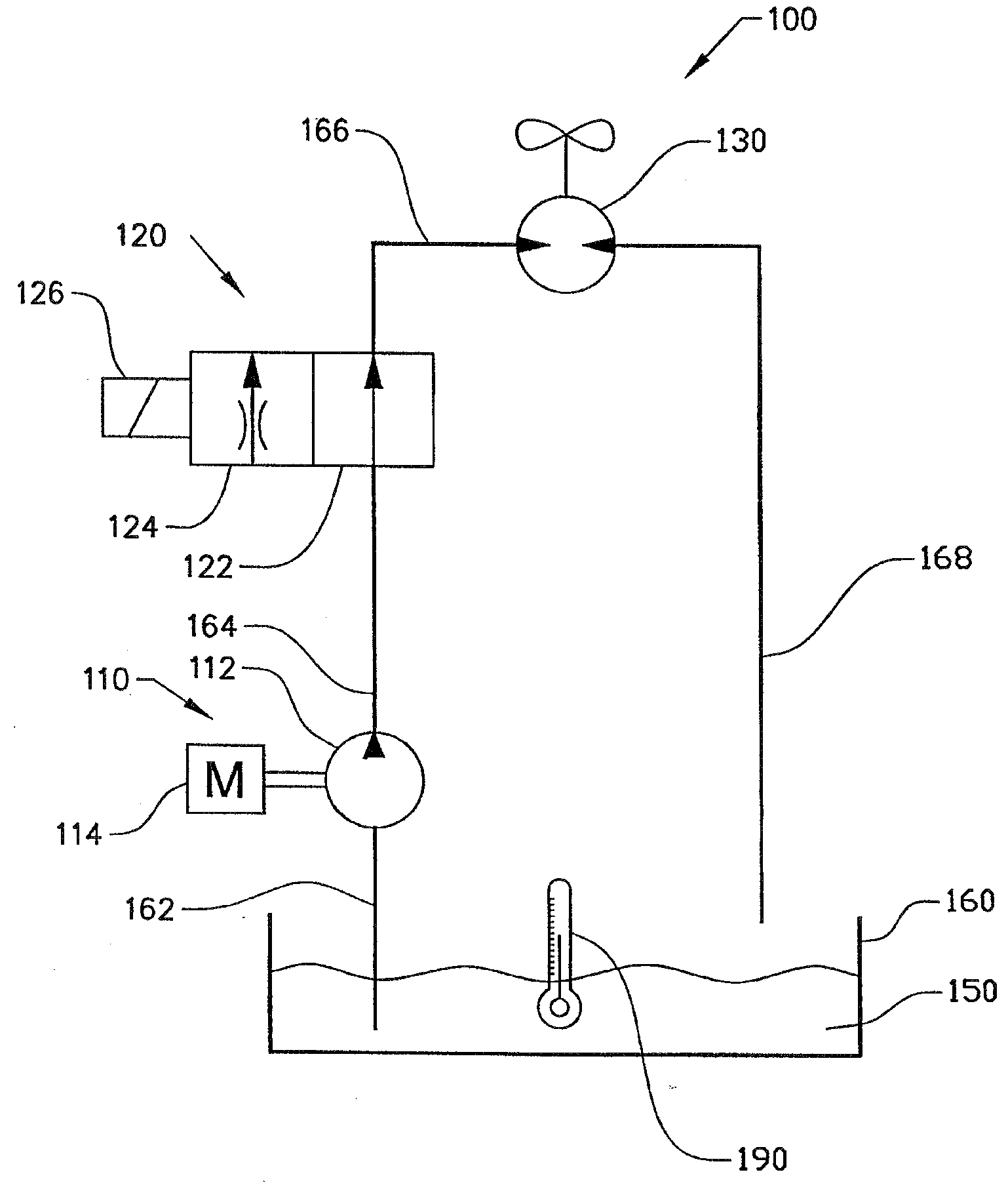
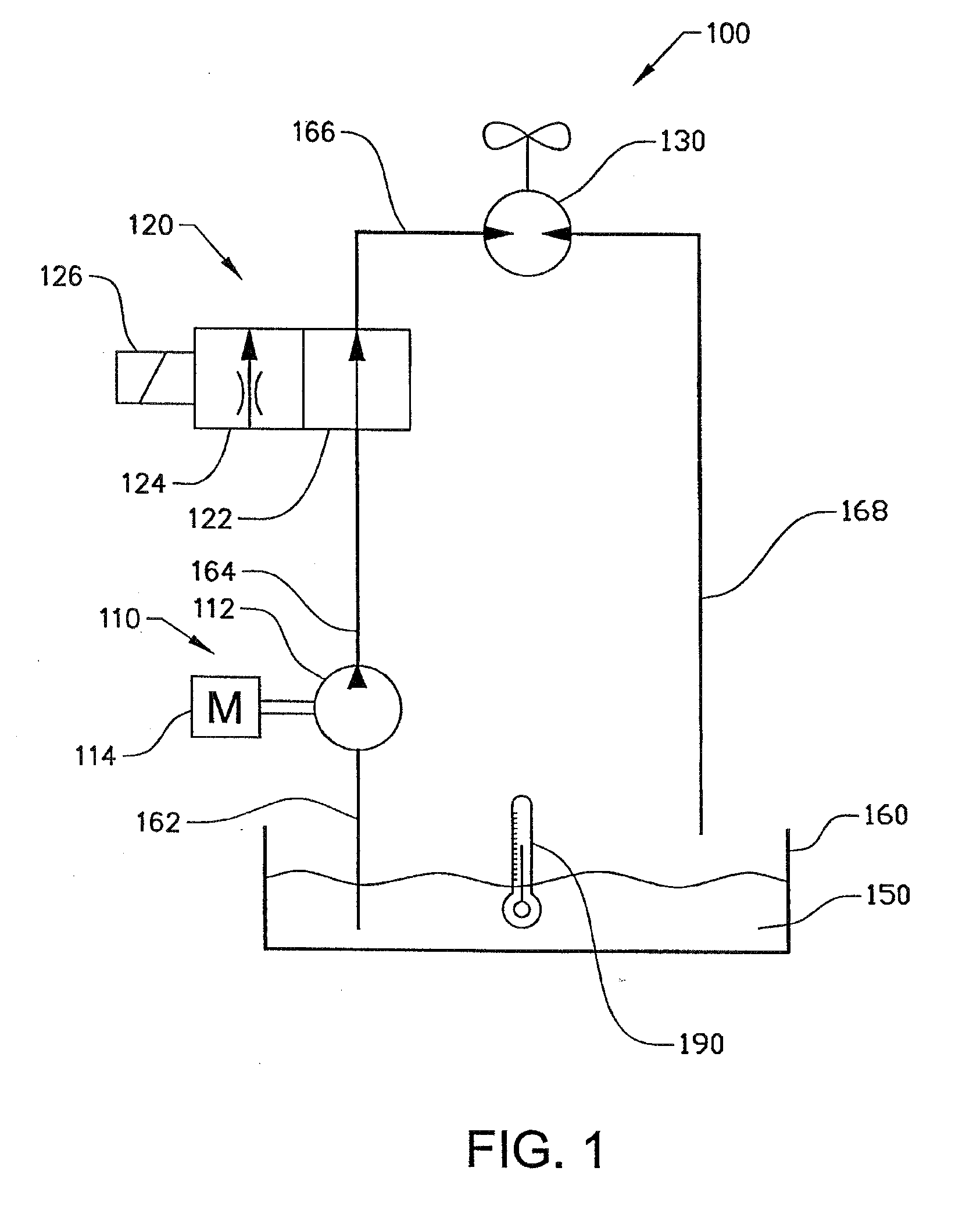
[0043] Machinery with hydraulic systems requires a certain viscosity of the hydraulic fluid in order to function satisfactorily. The temperature is the single most important factor affecting the viscosity of the hydraulic fluid. The viscosity-controlling method according to the invention is thus designed so that the hydraulic fluid can reach an operating temperature which results in the hydraulic fluid having a desired viscosity. Problems arise in most cases with machinery operating in cold climates, for example snow-clearers. It may also unfortunately happen that the operating hydraulics are seldom used or used only sporadically, which has the result that there is no self-heating of the hydraulic fluid in the hydraulic system. Self heating of the hydraulic fluid to a large extent arises through a pressure drop, which results in a power drain, on the one hand as mechanical work and on the other hand as heat. The part resulting in heat, which affords self-heating, are dissipations in...


PUM


Abstract

The invention relates to a method and system for controlling viscosity of a hydraulic fluid. The viscosity of a hydraulic fluid is usually very much dependent on temperature. By using existing throttles which generate a pressure drop, the hydraulic fluid can be heated by creating a power drain in these existing throttles through a controlled increase of the pressure through them. By controlled heating, the viscosity of a hydraulic fluid can be controlled. According to the invention, the existing throttles are preferably cavity-preventing openings in valves.

Description

BACKGROUND AND SUMMARY [0001] The present invention is a continuation of PCT / SE2004 / 000484, filed Mar. 30, 2004, which claims priority to SE 0301136-8, filed Apr. 15, 2003, both of which are hereby incorporated by reference. [0002] The present invention relates to a system and a method for controlling viscosity of a fluid, in particular hydraulic fluid such as hydraulic oil. The method and the system are especially suitable for application in hydraulic systems of heavy vehicles such as loaders and snow-clearing equipment. [0003] Viscosity is one of the most important properties of a hydraulic fluid, especially in a hydraulic operating system. Viscosity is a value of the fluid's flow resistance, or, in other words, the inertia with which the fluid moves. When the viscosity is low, the fluid is thin and free-flowing. Conversely, when the viscosity is high, the fluid is then thick and sluggish. [0004] High viscosity of a hydraulic fluid results in a hydraulic system which is sluggish a...

Claims


Application Information

Patent Timeline
Patent Type & Authority Applications(United States)
IPC IPC(8): F16D31/02F15B21/0427F15B21/045G05D24/02
CPCG05D24/02F15B21/042F15B21/045F15B2211/66F15B2211/6343F15B2211/6651F15B21/0427F01P7/044F01P2025/32F15B21/04G05D24/00
Inventor VIGHOLM, BOSTRANDBERG, LENNART
Owner VOLVO CONSTR EQUIP
Why Eureka
Try Eureka