Eddy current measurement and correction in magnetic resonance imaging systems

a magnetic resonance imaging and eddy current technology, applied in the field of magnetic resonance imaging systems, can solve problems such as image distortion resulting from overcompensation, image artifacts or distortion, and undercompensation still occurring

Active Publication Date: 2006-02-02
GENERAL ELECTRIC CO
View PDF31 Cites 29 Cited by
  • Summary
  • Abstract
  • Description
  • Claims
  • Application Information

AI Technical Summary

Benefits of technology

[0007] In some aspects, the present invention therefore provides a method for measuring and correcting for eddy currents in a magnetic imaging system. The method includes turning at least a portion of a pre-emphasis system of the magnetic imaging system off and running a pulse sequence using bipolar gradients to acquire a phase-difference image and a phase response of a static phantom that fills a majority of a field of view (FOV) of the magnetic imaging system. The method further includes fitting the phase difference image to a two-dimensional second order polynomial, changing the pulse sequence to provide a different delay, and iterating the running a pulse sequence and fitting the phase difference image and phase response a plurality of times with different delays to determine coefficients of the second order polynomial and a time constant of the phase response. The method also includes correcting the pre-emphasis system in accordance with the time constant of the phase response; determining an amplitude of correction to reduce the determined coefficients and storing the determined corrections in the pre-emphasis system.
[0008] In other aspects, the present invention provides a method for measuring and correcting for eddy currents in a magnetic imaging system. The method includes turning off short time constant pre-emphasis corrections of the magnetic imaging system, including time constants between 1 and 20 ms and running a pulse sequence using bipolar gradients to acquire a phase-difference image and a phase response of a static phantom that fills a majority of a field of view (FOV) of the magnetic imaging system. The method also includes fitting the phase difference image to a two dimensional second order polynomial φ(x,y) written φ(x,y)=a+b·x+c·y+d·x2+e·y2+f·x·y, where x and y correspond to two dimensions of the acquired image, and a, b, c, d, e, and f are coefficients to be fitted, and changing the pulse sequence to provide a different delay. The method also includes iterating the running a pulse sequence and fitting the phase difference image and phase response with different delays to determine coefficients of the second order polynomial and a time constant of the phase response. The method also includes correcting the pre-emphasis system in accordance with the time constant of the phase response, determining an amplitude of correction to reduce the determined coefficients, and storing the determined corrections in the pre-emphasis system.
[0009] In yet other aspects, the present invention provides a method for measuring and correcting for eddy currents in a magnetic imaging system. In these aspects, the method includes running a pulse sequence using bipolar gradients to acquire a phase-difference image and a phase response of a static phantom that fills a majority of a field of view (FOV) of the magnetic imaging system, fitting the phase difference image to a two-dimensional second order polynomial, and changing the pulse sequence to provide a different delay. The method further includes iterating the running a pulse sequence and fitting the phase difference image and phase response with different delays to determine coefficients of the second order polynomial and a time constant of the phase response. The method also includes correcting a pre-emphasis system of the magnetic imaging system in accordance with the time constant of the phase response, determining an amplitude of correction to reduce the determined coefficients, and storing the determined corrections in the pre-emphasis system.
[0010] In other aspects, the present invention provides a method for measuring and correcting for eddy currents in a magnetic imaging system. The method includes turning at least a portion of a pre-emphasis system of the magnetic imaging system off, running a pulse sequence using bipolar gradients to acquire a phase-difference image and a phase response of a static phantom that fills a majority of a field of view (FOV) of the magnetic imaging system, and linearly fitting the phase difference image to a two-dimensional polynomial. The method further includes changing the pulse sequence to provide a different delay, iterating the running a pulse sequence and the fitting the phase difference image and phase response a plurality of times with different said delays to determine coefficients of the polynomial and a time constant of the phase response, and correcting the pre-emphasis system in accordance with the time constant of the phase response. Additionally, the method includes determining an amplitude of correction to reduce the determined coefficients and storing the determined corrections in the pre-emphasis system.

Problems solved by technology

In modern MRI systems, a fast switching gradient subsystem and a conducting (typically metallic) structure of the MRI scanner couple together and generate substantial eddy currents that can lead to image artifacts or distortion.
However, image distortion resulting from overcompensation and undercompensation can still occur.
Recent reports suggest that flow-quantization using Phase Contrast (PC) imaging has worse performance on contemporary scanners than on previous generation scanners that have slower gradients.
However, if there is uncompensated eddy current, there will be different amount of extra phase accumulation during the two acquisitions.
As a result of the spurious phase difference, there is also an error in flow or velocity measurement.

Method used


Image

  • Eddy current measurement and correction in magnetic resonance imaging systems
  • Eddy current measurement and correction in magnetic resonance imaging systems
  • Eddy current measurement and correction in magnetic resonance imaging systems

Examples


Embodiment Construction

[0018] In various configurations, the present invention provides technical effects that include improved calibration of magnetic imaging systems that not only benefit clinical applications using phase contrast imaging as well as other application or sequences that are affected by eddy currents having short time constants.

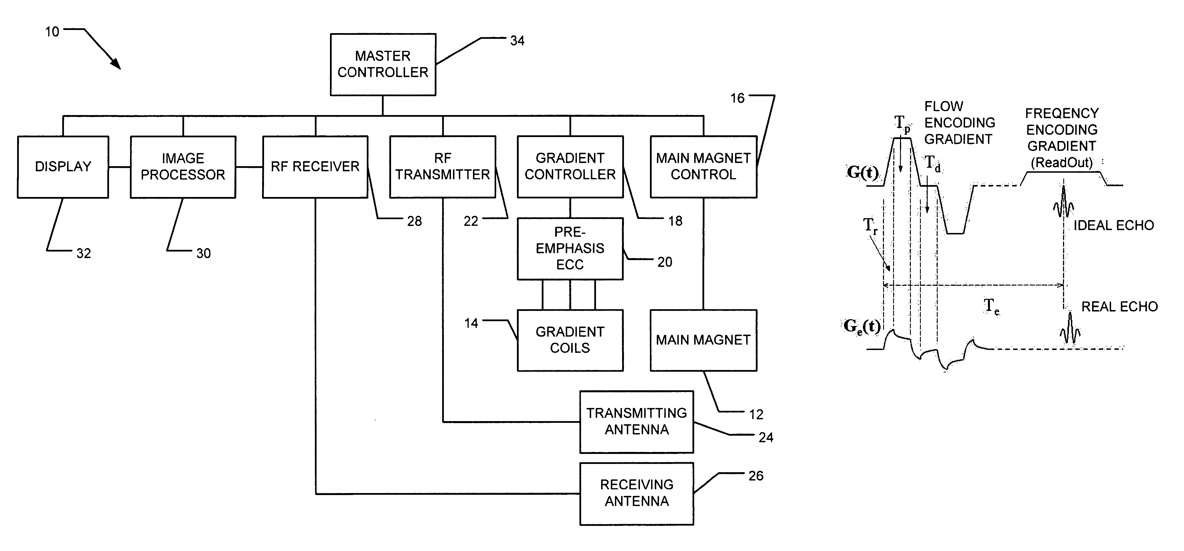
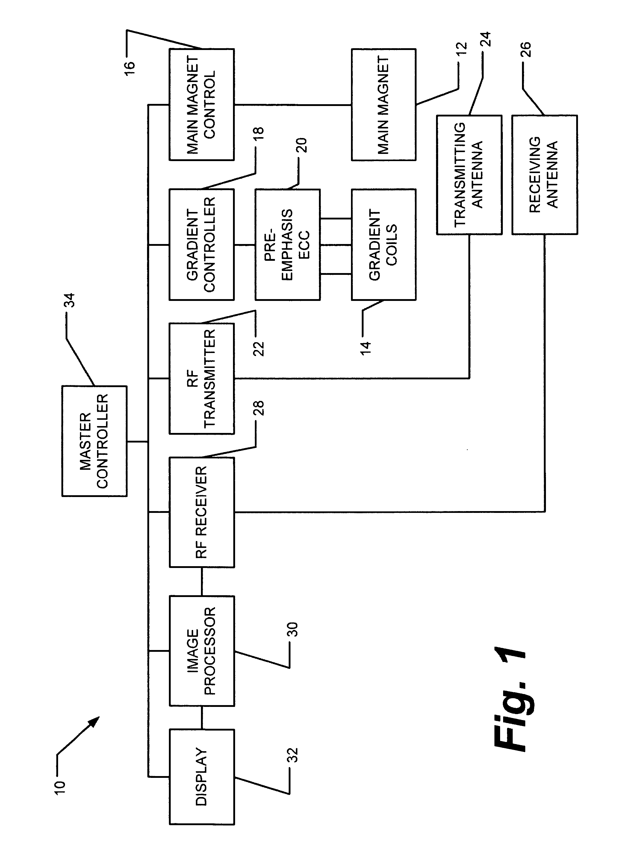
[0019] In some configurations of the present invention and referring to the block diagram of FIG. 1, a magnetic resonance imaging apparatus 10 includes a main magnet 12 and a set of one or more gradient coils 14. The operation of main magnet 12 is under control of main magnet controller 16. A gradient controller 18 controls the operation of gradient coils 14. Gradient controller 18 produces current pulses to gradient coils 14, thereby producing magnetic field pulses having a preselected profile. However, as a result of eddy current fields, the profiles of the magnetic field pulses are distorted relative to the current pulses applied to gradient coils 14. The distor...


PUM


Abstract

Measuring and correcting for eddy currents in a magnetic imaging system includes running a pulse sequence using bipolar gradients to acquire a phase-difference image and a phase response of a static phantom that fills a majority of a field of view (FOV) of the magnetic imaging system, fitting the phase difference image to a two-dimensional second order polynomial, and changing the pulse sequence to provide a different delay. The method further includes iterating the running a pulse sequence and fitting the phase difference image and phase response with different delays to determine coefficients of the second order polynomial and a time constant of the phase response. The method also includes correcting a pre-emphasis system of the magnetic imaging system in accordance with the time constant of the phase response, determining an amplitude of correction to reduce the determined coefficients, and storing the determined corrections in the pre-emphasis system.

Description

BACKGROUND OF THE INVENTION [0001] This invention relates generally to magnetic resonance imaging (MRI) systems, and more particularly to methods for compensating for eddy currents existing in MRI systems. [0002] Eddy currents are electric currents generated in a conducting structure by rapidly changing magnetic fields. In modern MRI systems, a fast switching gradient subsystem and a conducting (typically metallic) structure of the MRI scanner couple together and generate substantial eddy currents that can lead to image artifacts or distortion. At least one known superconducting MRI system is equipped with a pre-emphasis system that compensates for the eddy current effect. However, image distortion resulting from overcompensation and undercompensation can still occur. At least one known method for eddy current measurement based on the Free Induction Decay (FID) techniques is known not to be very sensitive to currents with short time constants on the order of 1 to 4 ms. [0003] Recent...

Claims


Application Information

Patent Timeline
Patent Type & Authority Applications(United States)
IPC IPC(8): G01V3/00
CPCG01R33/56518
Inventor ZHOU, YONGKING, KEVIN FRANKLIN
Owner GENERAL ELECTRIC CO
Why Eureka
Try Eureka