
Polymer stabilized electrically controlled birefringence transflective LCD

a technology of transflective liquid crystal displays and polymer stabilized materials, applied in optics, non-linear optics, instruments, etc., can solve the problems of unreadable reflective lcds, reflective lcds becoming more difficult to read, reflective lcds consuming very low power, etc., and achieve the effect of improving device stability

Active Publication Date: 2006-02-02
KENT STATE UNIV
View PDF14 Cites 45 Cited by
  • Summary
  • Abstract
  • Description
  • Claims
  • Application Information

AI Technical Summary

Benefits of technology

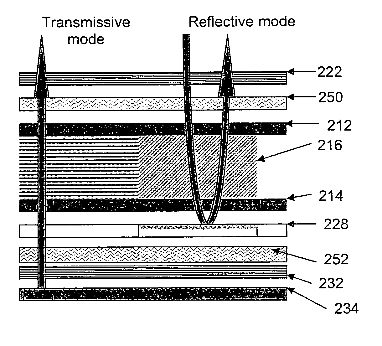
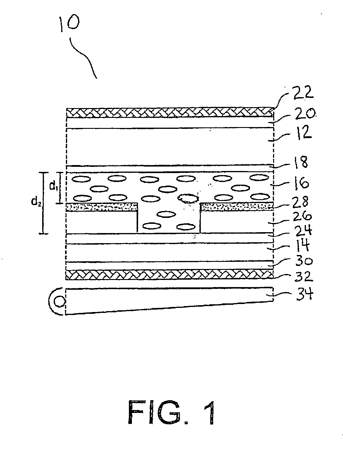
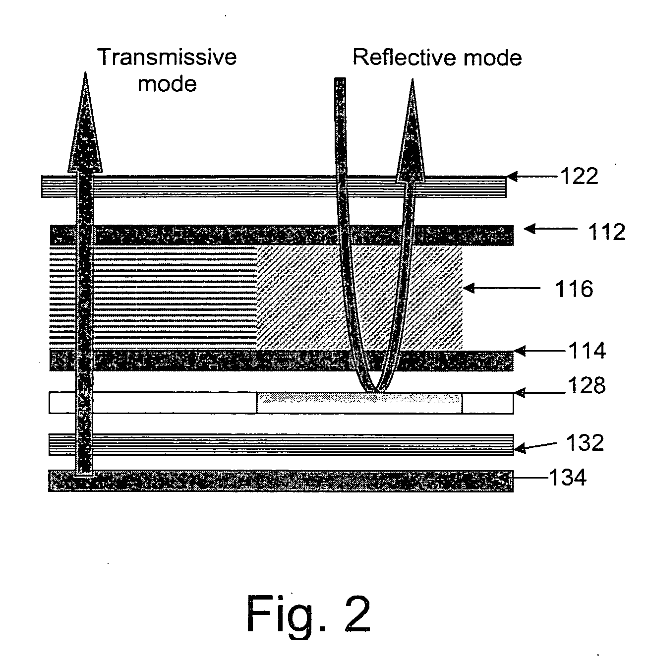
[0018] In a second exemplary embodiment, there is provided a method for creating a polymer stabilized liquid crystal display, including the steps of providing a display cell including two parallel substrates and a plurality of transmissive and reflective pixels; filling the display cell with a mixture of liquid crystal, monomer and, optionally, a photo-initiator; subsequently, curing the monomer in one of the transmissive or reflective pixels while applying a voltage across them while the monomer in the other of the transmissive or reflective pixels is prevented from curing; and curing the monomer in the other of the transmissive or reflective pixels while applying a different voltage.

Problems solved by technology

In very bright outdoor environments they tend to “wash out” and become unreadable due to the reflection of the sun from the surface of the LCD overwhelming the light being transmitted through the display.
Reflective LCDs consume very low power (especially without a front light) and are often used in small portable devices such as handheld games, PDA's or other portable instrumentation.
Under dim lighting conditions, reflective LCDs become more difficult to read due to the absence of a strong light source to illuminate the pixels.
In any other arrangement, the two modes will interfere with each other, resulting in a low contrast ratio.
This feature of different optical paths of the two modes makes it difficult to synchronize their operation.
Although the operation of the two modes is synchronized in the display, it is a difficult process to fabricate alternating pixels with two thicknesses.

Method used


Image

  • Polymer stabilized electrically controlled birefringence transflective LCD
  • Polymer stabilized electrically controlled birefringence transflective LCD
  • Polymer stabilized electrically controlled birefringence transflective LCD

Examples


examples

[0051] A mixture of nematic liquid crystal ZLI-4469-100 96.7 wt % (available from Merck), a mesogenic diacrylate monomer 3 wt % (lab. made) and photo-initiator benzyl methyl ether 0.3 wt % (available from Polyscience). The mixture was filled into cells consisting of two parallel glass plates with the cell gap of 5 micron. The cells had homogeneous alignment layers. The cells were irradiated under UV light to polymerize the monomer at various voltages. At zero voltage, the liquid crystal oriented parallel to the cell surface along the rubbing direction of the alignment layer. When a voltage above zero was applied to cell, the liquid crystal was tilted toward the normal direction of the cell. The higher the applied voltage, the more the liquid crystal was tilted toward the normal direction. The polymer network formed favored the state in which the polymerization took place.

[0052] After curing, the electro-optical properties of the cells were measured using a He—Ne laser with the wave...


PUM

PropertyMeasurementUnit
Percent by massaaaaaaaaaa
Weightaaaaaaaaaa
Thicknessaaaaaaaaaa

Abstract

A transreflective display in which the thickness of the liquid crystal layer is the same for both transmissive and reflective modes. The transmissive and reflective pixels are stabilized in two different liquid crystal configurations with different birefringences. The light retardation effect of one path in the transmissive pixels is close to or equals the retardation effect of two paths in the reflective pixels, resulting in synchronization of the two modes.

Description

[0001] This application claims benefit of the filing date of and priority from U.S. provisional application Ser. No. 60 / 592,316 filed on Jul. 29, 2004.BACKGROUND [0002] The present exemplary embodiments relate to liquid crystal displays. It finds particular application in conjunction with polymer stabilized transflective liquid crystal displays, and will be described with particular reference thereto. However, it is to be appreciated that the present exemplary embodiments are also amenable to other like applications. [0003] Liquid crystal displays (LCD's) can be described as being one of three basic types: transmissive, reflective or transflective. In transmissive construction, all of the light seen by the user is transmitted through the LCD from a backlight. Typically, the LCD pixels are illuminated from behind the display using a cold cathode fluorescent lamp (CCFL) or LED. [0004] Transmissive LCDs offer wide color gamut, high contrast and are typically used in laptop personal com...

Claims


Application Information

Patent Timeline
IPC IPC(8): G02F1/1335
CPCG02F2001/13775G02F1/133555G02F1/13775
Inventor YANG, DENG-KEZHOU, FUSHAN
Owner KENT STATE UNIV
Learn More