Optical characteristic analysis method, sample measuring apparatus and spectroscopic ellipsometer

Inactive Publication Date: 2006-02-02
HORIBA LTD
View PDF2 Cites 17 Cited by
  • Summary
  • Abstract
  • Description
  • Claims
  • Application Information

AI Technical Summary

Benefits of technology

[0010] The present invention has been made with the aim of solving the above problems, and it is an object of the present invention to provide an optical characteristic analysis method, a sample measuring apparatus and a spectroscopic ellipsometer, with which the optical

Problems solved by technology

In the conventional measurement method shown in FIG. 1, since a measurement is made with the prism coupling P being placed on the surface of the sample S, there is a problem that a sample S of large size, having a dimension at least sufficient for placing the prism coupling P, needs to be prepared.
Moreover, since it is necessary to polish the surface of the sample S, on which the prism coupling P is placed, until a required smoothness is obtained, in order to prevent occurrence of unwanted refraction at the boundary between the prism coupling P and the sample S, there is a problem that preparation of the sample S needs a lot of effort.
Furthermore, since a me

Method used


Image

  • Optical characteristic analysis method, sample measuring apparatus and spectroscopic ellipsometer
  • Optical characteristic analysis method, sample measuring apparatus and spectroscopic ellipsometer
  • Optical characteristic analysis method, sample measuring apparatus and spectroscopic ellipsometer

Examples


Embodiment Construction

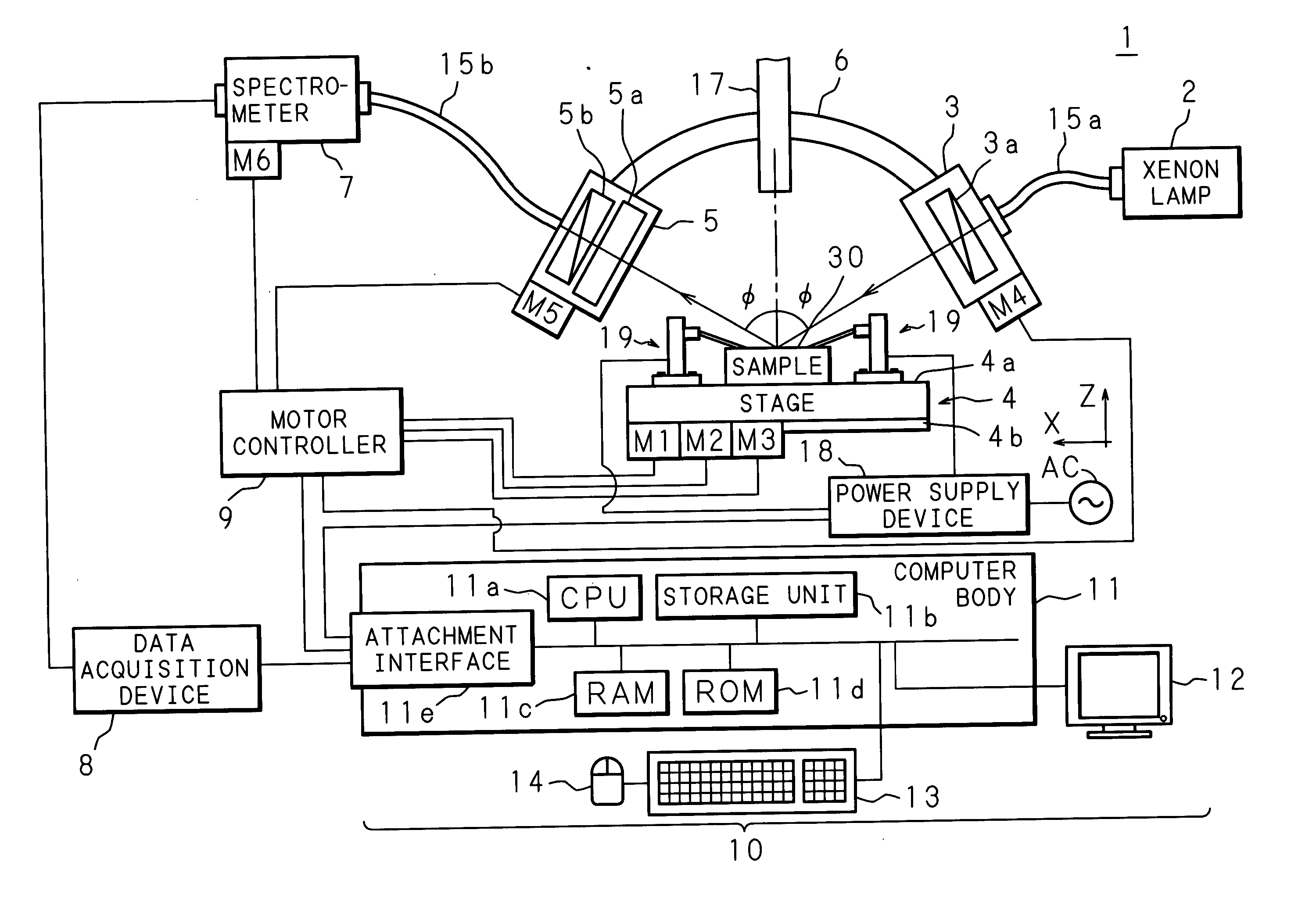
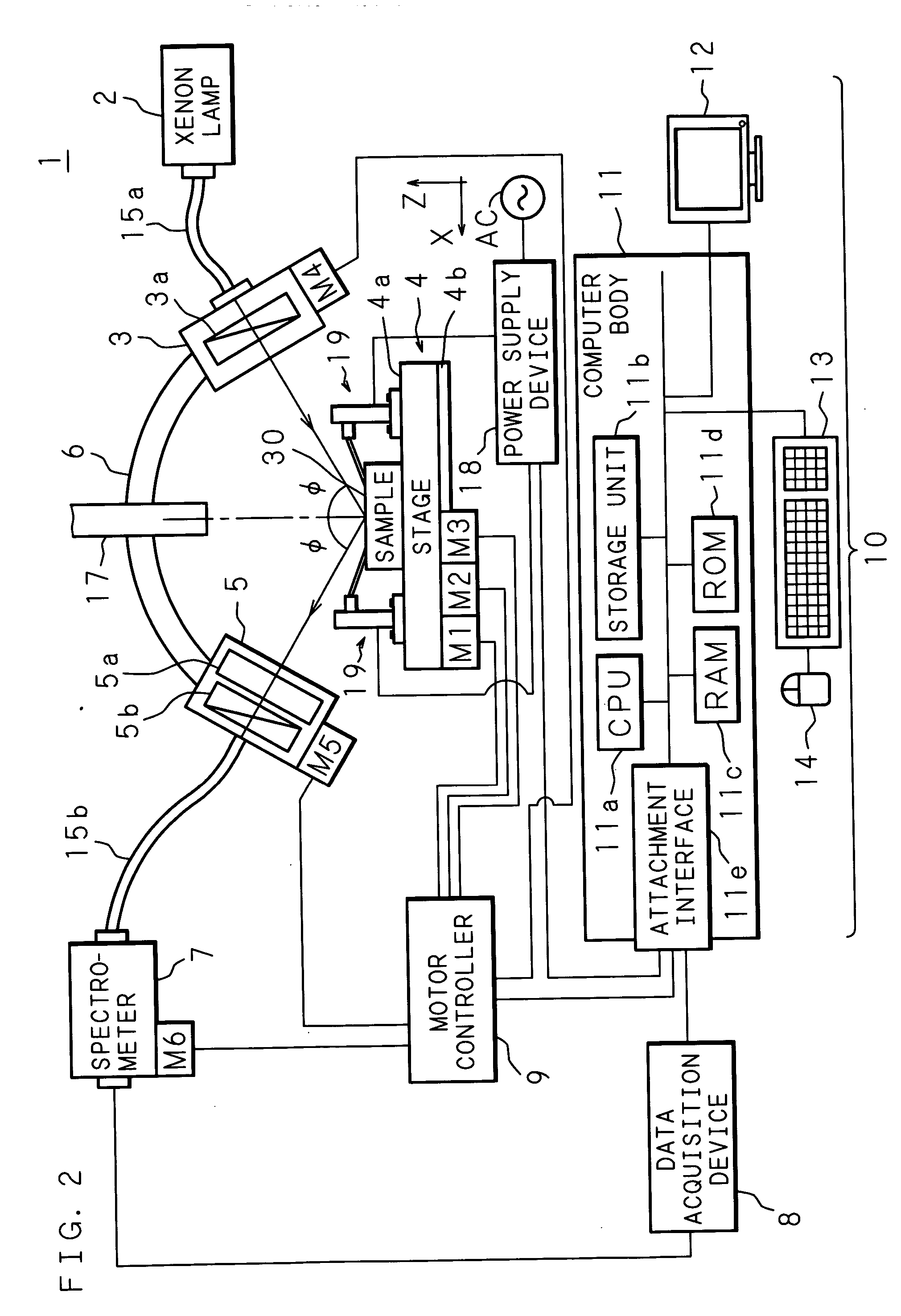
[0048]FIG. 2 is a schematic view showing the general structure of a spectroscopic ellipsometer 1 according to an embodiment of the present invention. The spectroscopic ellipsometer 1 is constructed to analyze the optical characteristic of a sample 30 for each layer and to evaluate the electro-optic effect, by generating electric field at the sample 30 having a multilayer film structure and irradiating polarized light. The spectroscopic ellipsometer 1 of the present embodiment comprises a power supply device 18 and a pair of conducting probe stands 19, as voltage applying means for applying voltage for generating electric field at the sample 30.

[0049] Although the spectroscopic ellipsometer 1 can analyze a variety of samples as an object of evaluation, in the present embodiment, as shown in FIGS. 3A and 4, the object of evaluation is the sample 30 constructed by forming a PLZT film 32 on an Si (silicon) substrate 31, which has a Pt (platinum) film provided on the surface thereof by ...


PUM


Abstract

The spectroscopic ellipsometer, by a computer program incorporated therein, applies voltage to a sample placed on a stage, with a power supply device and conducting probe stands, polarizes multi-wavelength light, with a light polarizer, generated by a xenon lamp and irradiates the polarized light to the sample. The sample is provided with a multilayer film and electrodes formed on a substrate and the sample's surface, and light reflected from the sample is received by the light receiver and measured by the spectrometer. The computer analyzes the optical characteristic of the sample individually for each layer of the multilayer film on the basis of the measurement result and a value calculated from a model which is formed according to the sample structure.

Description

CROSS-REFERENCE TO RELATED APPLICATIONS [0001] This Nonprovisional application claims priority under 35 U.S.C. §119(a) on Patent Application No. 2004-225991 filed in Japan on Aug. 2, 2004, the entire contents of which are hereby incorporated by reference. BACKGROUND OF THE INVENTION [0002] 1. Field of the Invention [0003] The present invention relates to an optical characteristic analysis method, a sample measuring apparatus and a spectroscopic ellipsometer, with which the optical characteristic of a multilayer film can be analyzed, with voltage being applied thereto, in order to evaluate the electro-optic effect of the material with a multilayer film structure. [0004] 2. Description of Related Art [0005] Conventionally, a substance provided with a high-dielectric constant film or a ferroelectric film, formed on a substrate, is used as the material to produce a ferroelectric memory, a ferroelectric capacitor, a piezoelectric element, such an actuator, and an electro-optic device, su...

Claims


Application Information

Patent Timeline
IPC IPC(8): G01J4/00
CPCG01N21/1717G01N2021/213G01N21/211
Inventor FUNAKUBO, HIROSHIHONDA, YOSHIHISANABATOVA-GABAIN, NATALIYATERAI, ASUKA
Owner HORIBA LTD
Why Eureka
Try Eureka