Self refresh period control circuits

a control circuit and self-refresh technology, applied in the field of self-refresh period control circuits, can solve problems such as data loss and improper operation of refresh characteristics based on temperatur

Inactive Publication Date: 2006-02-02
SAMSUNG ELECTRONICS CO LTD
View PDF11 Cites 77 Cited by
  • Summary
  • Abstract
  • Description
  • Claims
  • Application Information

AI Technical Summary

Problems solved by technology

However, leakage current is caused in a DRAM cell by a PN junction of MOS (Metal Oxide Semiconductor) transistor etc., and an initially stored charge volume is lost, thus data may be lost.
In other words, at section I from the time of the generation of the self refresh start signal SRS,enter to a time prior to generation of the period control signal TS through a temperature sensing of the temperature sensor 12; a self refresh is performed by a refresh period of a previously generated period control signal TS, thus there is a problem during this time period that operation is improper for refresh characteristics based on temperature.

Method used


Image

  • Self refresh period control circuits
  • Self refresh period control circuits
  • Self refresh period control circuits

Examples


Embodiment Construction

[0048] The present invention will now be described more fully hereinafter with reference to the accompanying drawings, in which preferred embodiments of the invention are shown. This invention may, however, be embodied in different forms and should not be construed as limited to the embodiments set forth herein. Like numbers refer to like elements throughout the specification.

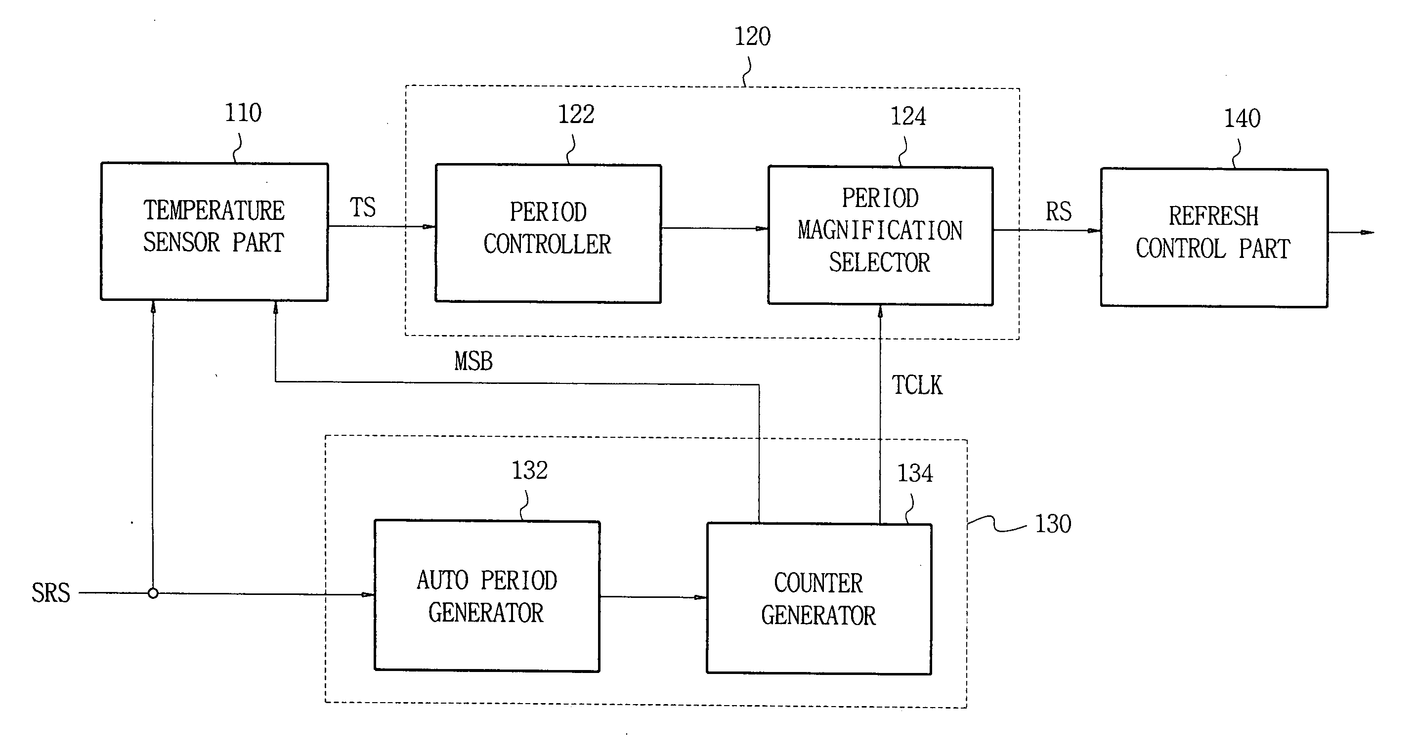
[0049]FIG. 4 is a block diagram of self refresh period control circuit according to an exemplary embodiment of the invention

[0050] Referring to FIG. 4, a self refresh period control circuit according to an exemplary embodiment includes a temperature sensor part 110, a period magnification control part 120, a clock generating part 130 and a refresh control part 140.

[0051] The temperature sensor part 110 generates a first period control signal TS in response to a self refresh start signal SRS or self refresh completion signal SRS, senses the temperature of a semiconductor memory device provided with the instal...


PUM


Abstract

In a self refresh period control circuit for controlling a refresh period of a semiconductor memory device in response to operating temperature of the device, a temperature sensor part generates a first period control signal in response to a self refresh start signal or self refresh completion signal, senses operating temperature of the semiconductor memory device in response to a clock signal generated by the self refresh start signal, and generates a corresponding second period control signal. A period magnification control part controls a self refresh period in response to the first and second period control signals. Accordingly, a refresh period characteristic change based on operating temperature, which is causable by an initial self refresh, is implemented.

Description

CROSS REFERENCE TO RELATED APPLICATIONS [0001] This application claims priority under 35 U.S.C. §119 to Korean Patent Application 2004-59567, filed on Jul. 29, 2004, the contents of which are hereby incorporated by reference in their entirety. BACKGROUND OF THE INVENTION [0002] 1. Technical Field [0003] The present invention relates to a semiconductor memory device, and more particularly, to a self refresh period control circuit capable of controlling a refresh period in response to a temperature change in a manner that reduces current consumption and improves consumer reliability. [0004] 2. Description of the Background of the Invention [0005] Semiconductor memory devices can generally be categorized as volatile memory devices and nonvolatile memory devices according to the retention or non-retention of data when an external power source is removed. Volatile memory devices include DRAM (Dynamic Random Access Memory) and SRAM (Static Random Access Memory), etc. Non-volatile memory d...

Claims


Application Information

Patent Timeline
Patent Type & Authority Applications(United States)
IPC IPC(8): G11C7/00
CPCG11C11/406G11C2211/4061G11C11/40626G11C7/04G11C11/40615G11C11/4076G11C2211/4067
Inventor PARK, SANG-KYUN
Owner SAMSUNG ELECTRONICS CO LTD
Why Eureka
Try Eureka