Concrete polishing system

a concrete and concrete technology, applied in the direction of grinding heads, manufacturing tools, grinding machines, etc., can solve the problems of uneven concrete floors, unsightly concrete floors with polished portions and other parts rough, and high cost of time and material for the polishing or grinding process

Inactive Publication Date: 2006-02-02
GUEORGUIEV GUEORGUI D +1
View PDF14 Cites 52 Cited by
  • Summary
  • Abstract
  • Description
  • Claims
  • Application Information

AI Technical Summary

Benefits of technology

[0009] It is an object of the present invention to provide a flexible mounting of the abrasive unit tha

Problems solved by technology

Despite the most skilled of floor finishers concrete floors are not perfectly flat.
This leaves an unsightly floor with portions polished and other portions rough.
Often this exposes aggregate, or rock filler, in the concrete.
Yet another problem with the prior art is the high cost associated with time and material for the polishing or grinding process.
The multiple operations are time consuming.
The course abrasive units ty

Method used


Image

  • Concrete polishing system
  • Concrete polishing system
  • Concrete polishing system

Examples


Embodiment Construction

[0029] The invention will be described with reference to the various figures. The figures represent part of the present disclosure but are not intended to limit the scope of the invention. Within the various figures similar elements will be numbered accordingly.

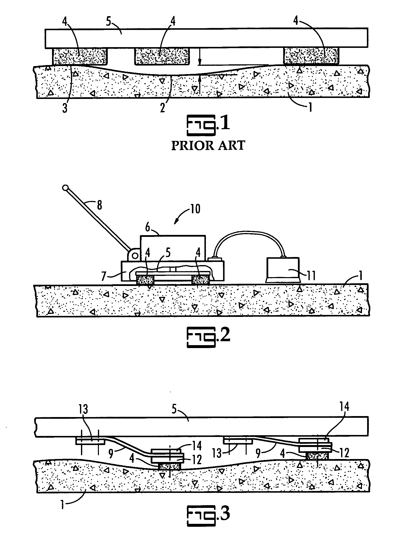
[0030] A floor polisher is illustrated in FIG. 2. In FIG. 2, the floor polisher, 10, comprises abrasive units, 4, mounted on a plate, 5. A motor, 6, rotates the plate, 5. An operator then moves the floor polisher, 10, across the floor by grasping the handle, 8. The combination of the rotating plate and movement of the floor polisher allows the entire surface area to be polished. An optional shroud, 7, assists in decreasing the dust emanating from under the floor polisher. An optional vacuum dust collection system, 11, can be employed as known in the art.

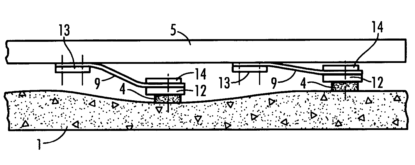
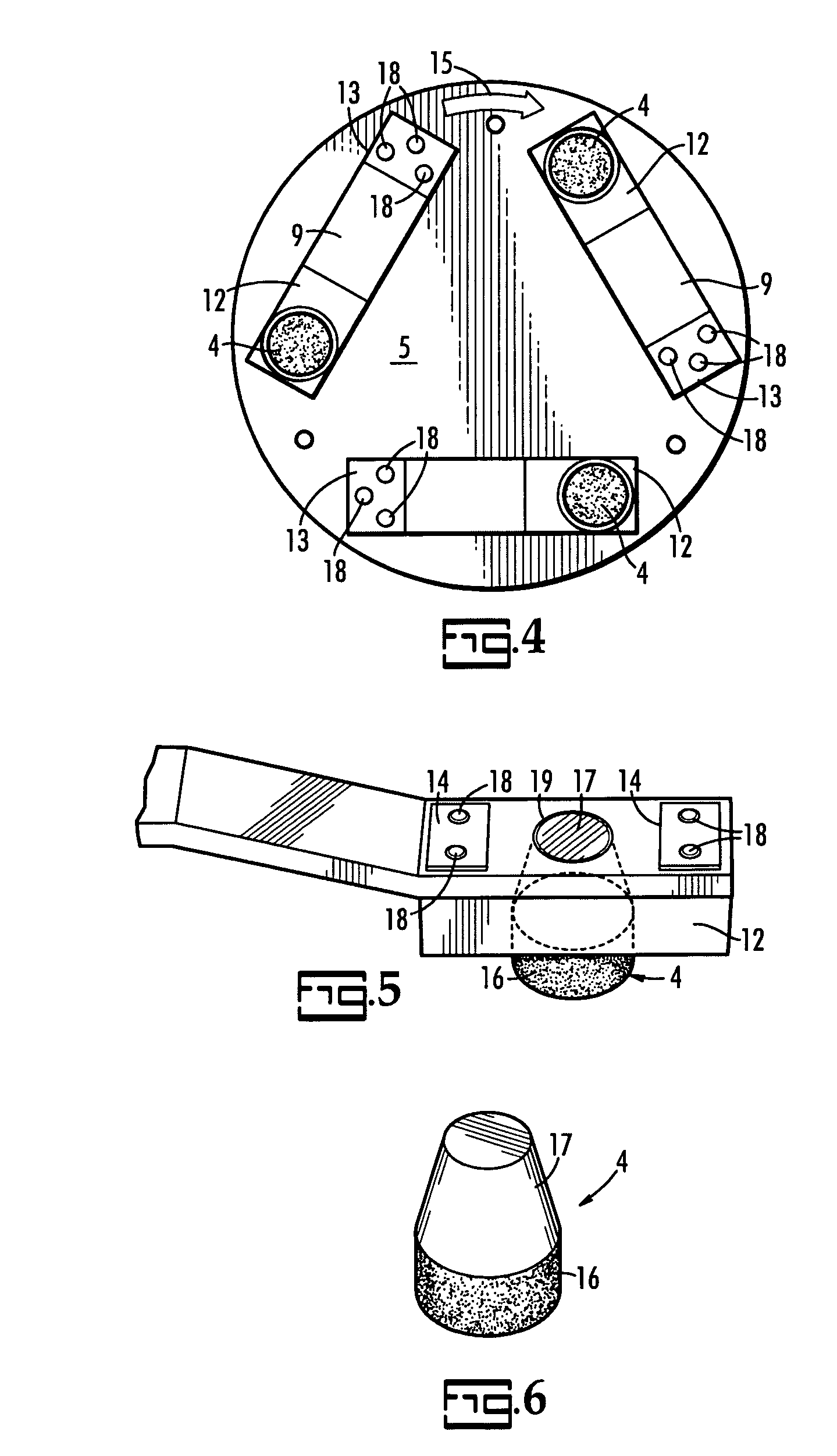
[0031]FIG. 3 is a partial side view of the present invention. In FIG. 3, the plate, 5, has mounted thereon a multiplicity of variable vertical displacement mounting devices ...


PUM


Abstract

A grinding machine abrasive unit holder with the use of springs, gases or fluids allows each abrasive unit to be in contact with the floor, independently at all times. This action allows the finishing of the high and low spots of the floor in the same operation.

Description

CROSS-REFERENCE TO RELATED APPLICATIONS [0001] The present application is a continuation in part application of U.S. patent application Ser. No. 10 / 900,786 filed Jul. 28, 2004 which is pending.BACKGROUND OF THE INVENTION [0002] The present invention is related to a system for polishing concrete. More particularly, the present invention is related to a system, and method, for polishing concrete without the typical problems of uneven polishing in the valleys and hills of poured concrete. [0003] Polishing concrete has been known for some time. The abrasive units of floor grinding machines are typically rigidly attached to the drive mechanism of the machine thus allowing the abrasive units to operate in a single plane. Despite the most skilled of floor finishers concrete floors are not perfectly flat. A typical technique for polishing concrete will be described with reference to FIG. 1. [0004] In FIG. 1, the concrete floor, 1, is uneven with valleys, 2, and hills, 3. The concrete floor,...

Claims


Application Information

Patent Timeline
IPC IPC(8): B24B23/00
CPCB24B7/186B24D7/18B24B41/047
Inventor GUEORGUIEV, GUEORGUI D.POPOV, GEORGI M.
Owner GUEORGUIEV GUEORGUI D
Why Eureka
Try Eureka