Recirculating vertical wind tunnel skydiving simulator

Active Publication Date: 2006-02-02
IFLY HLDG
View PDF9 Cites 34 Cited by
  • Summary
  • Abstract
  • Description
  • Claims
  • Application Information

AI Technical Summary

Benefits of technology

[0061] The air then passes into the inlet contractor. This trumpet-shaped or bell-shaped device quickly reduces the flow area and accelerates the air to its maxim

Problems solved by technology

Some of these have been converted or adapted for vertical operation (in which the air in the full speed section of the tunnel flows generally vertically) but most or all perform poorly in that role.
While it is possible to put a safety net on both the upstream and downstream ends of the flight chamber, these produce an enormous amount of drag which creates noise and increases the power required to attain any given speed.
In fact, such a pair of nets can consume as much as 30% to 50% of the total power required to operate such a wind tunnel.
Vertical wind tunnels used for freefall simulation often have to operate in noise sensitive environments such as amusement parks and shopping malls.
Finally no known prior art has focused on designing these systems to optimize visibility to public spectators in a shopping mall or other high density entertainment venue.
However, moving air through ductwork at high speeds creates an enormous amount of sound and heat and requires a

Method used


Image

  • Recirculating vertical wind tunnel skydiving simulator
  • Recirculating vertical wind tunnel skydiving simulator
  • Recirculating vertical wind tunnel skydiving simulator

Examples


Embodiment Construction

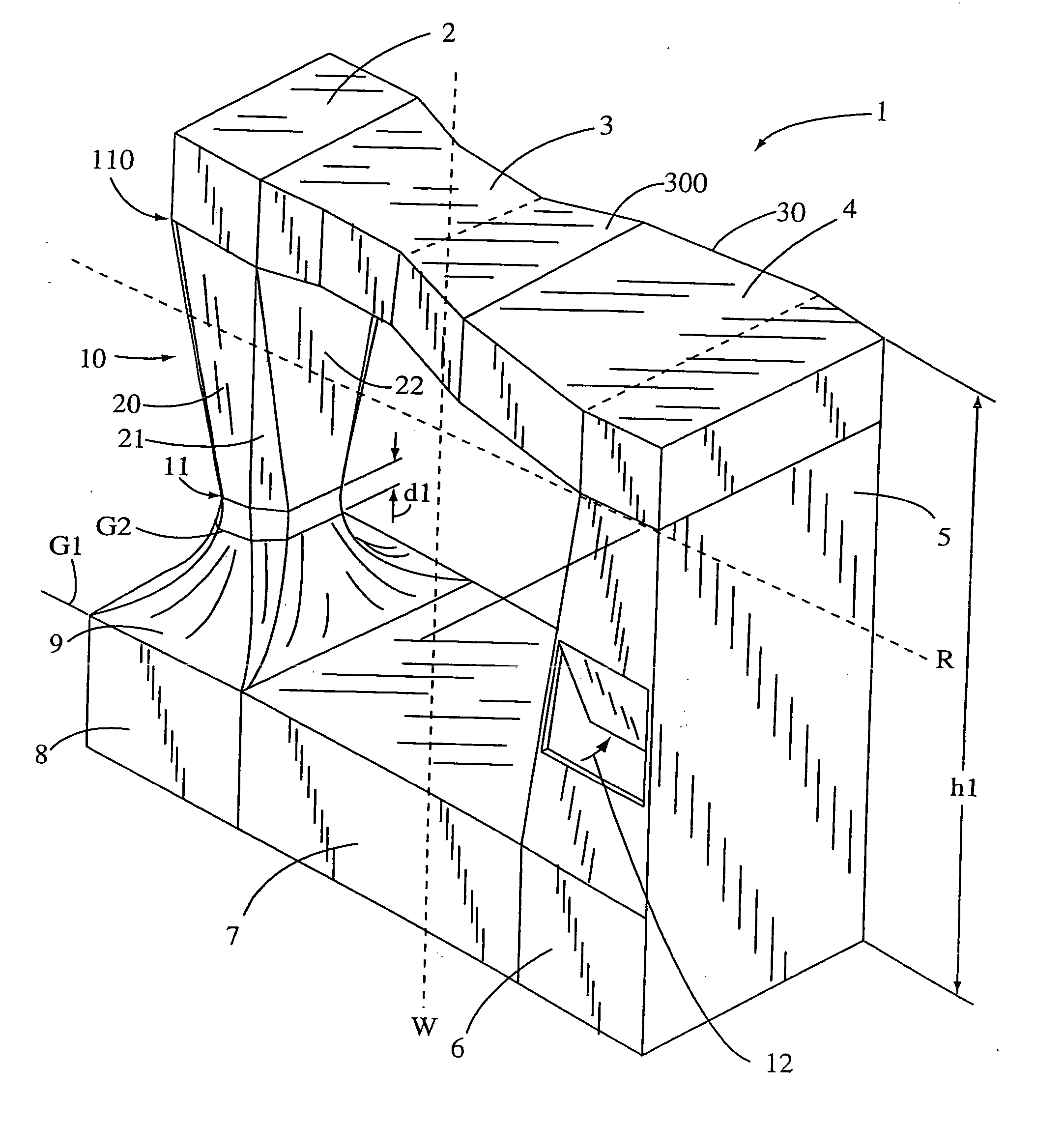
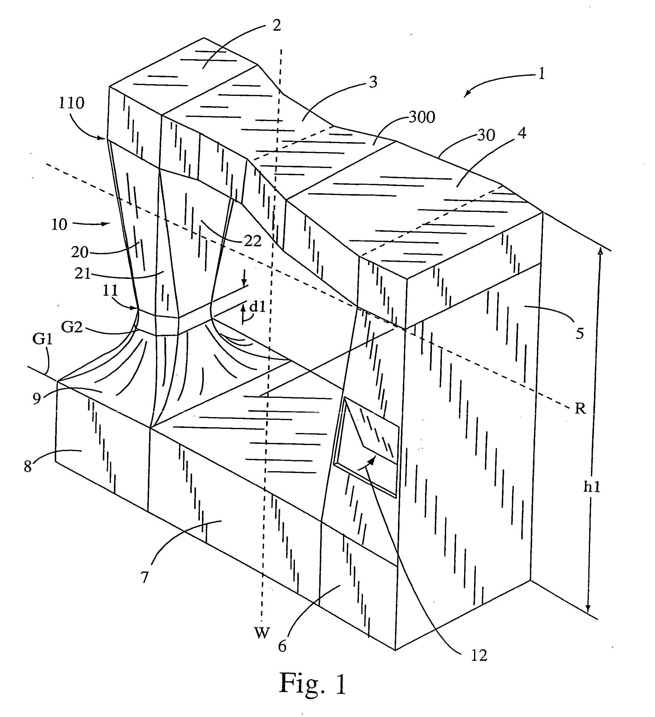
[0092] Referring first to FIG. 1 a single return simulator 1 is shown, wherein height L1 is preferably in the range of about 50-120 feet. Some installations may bury all components below a ground level of either G1 or G2. The flight chamber 10 may be made entirely or partially with transparent panels. If ground level is at G2, then an opaque pedestal-type image formed in area d1 which may be about seven feet high. This embodiment in a mall creates an eye-catching, live action human flight studio in the flight chamber 10. This design attracts new “fliers” who pay to experience simulated skydiving in flight chamber 10. Dotted line R represents a roof, wherein components above R can be roof-mounted to reduce noise. Dotted line W represents a wall, wherein components beyond the wall W away from the flight chamber 10 could be isolated from the flight chamber to reduce noise near the flight chamber 10.

[0093] Most prior art flight chambers provide for parallel walls in the flight chamber ...


PUM


Abstract

A vertical wind tunnel flight simulator comprises a flight chamber wherein a flier may experience a freefall simulation. Airflow to support the flier is induced by fans connected above the flight chamber through a duct. A staging area having openings to the flight chamber is adjacent to the flight chamber. One or two return air ducts are used to return air from the fans outlet to the fans inlet. Opposed louvers are included on at least one duct segment thereby regulating the temperature via forcing ambient air into the simulator. The use of many duct segments having diverging walls adds commercial value to the system by lowering the height. Mounting components on the roof and behind walls creates a spectacular pedestrian viewing scene of people in flight.

Description

CROSS REFERENCE PATENTS [0001] U.S. Pat. No. 6,083,110 is incorporated herein by reference. FIELD OF THE INVENTION [0002] The present invention relates to the field of vertical wind tunnels, more particularly, to temperature controlled return flow vertical wind tunnels used as skydiving simulators and amusement devices. BACKGROUND OF THE INVENTION [0003] Wind tunnels are well known in the art. Wind tunnels are available in many types and styles depending upon the needs of the user. These include subsonic wind tunnels with and without return flow, transonic wind tunnels with and without return flow, vertical subsonic wind tunnels with and without return flow, supersonic and hypersonic wind tunnels with and without return flow, and compressible flow wind tunnels. [0004] The majority of the wind tunnels are used for research and testing purposes. These include testing of conventional aircraft, helicopters, parachutes and other aerodynamic devices, wing surfaces, control surfaces, subma...

Claims


Application Information

Patent Timeline
IPC IPC(8): A63G31/00
CPCA63G31/00D07B5/005A63G2031/005B64D23/00G01M9/02
Inventor METNI, N. ALANKITCHEN, WILLIAM J.MORT, KENNETH W.EASTLAKE, CHARLES N.PALMER, MICHAEL
Owner IFLY HLDG
Why Eureka
Try Eureka