

Error correcting logic system
- Summary
- Abstract
- Description
- Claims
- Application Information
AI Technical Summary
Benefits of technology
Problems solved by technology
Method used
Image

Examples
first embodiment
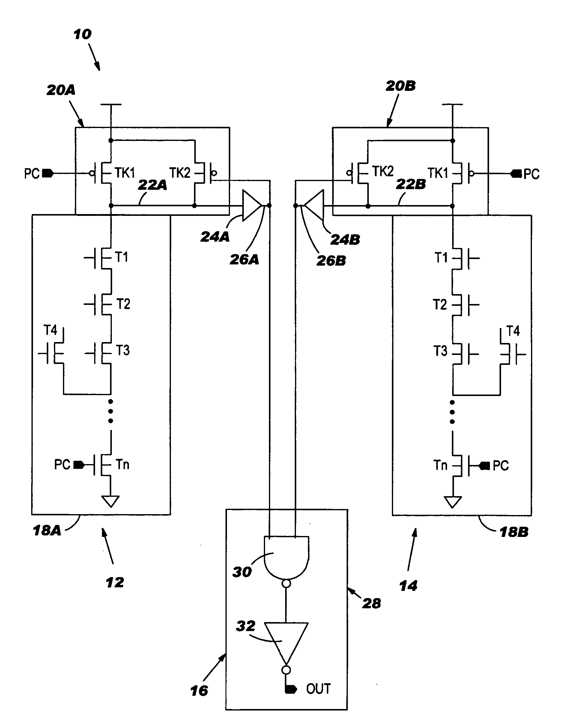
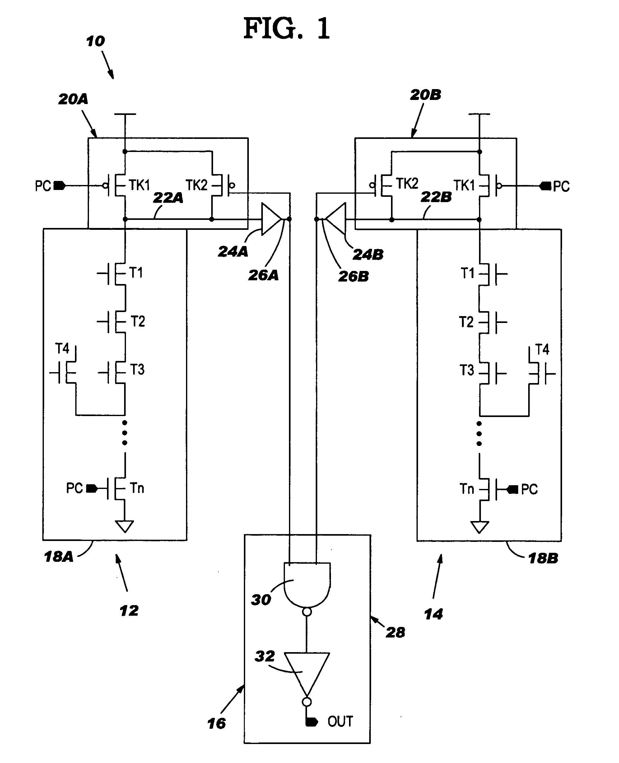
[0016] With reference to the accompanying drawings, FIG. 1 shows an error correcting logic system 10 according to the invention. System 10 includes a first dynamic logic gate 12 (hereinafter “DLG”), a second DLG 14, which is identical to first DLG 12, and an interconnecting gate 16 connected to receive the outputs of both DLGs 12, 14. A DLG, generally, outputs a first logic state that is generated by pre-charging of a node, and either maintains that first logic state or changes it to a second logic state in response to a logic input signal. For purposes of description, each dynamic logic gate has been illustrated as a cascode voltage switch (hereinafter “CVS”). It should be recognized, however, that the teachings of the invention are applicable to a variety of dynamic logic systems or mechanisms for evaluating a logic input signal. It should also be recognized that while two DLGs 12, 14 have been illustrated, the invention may include any number of DLGs 12, 14 feeding to an intercon...
second embodiment
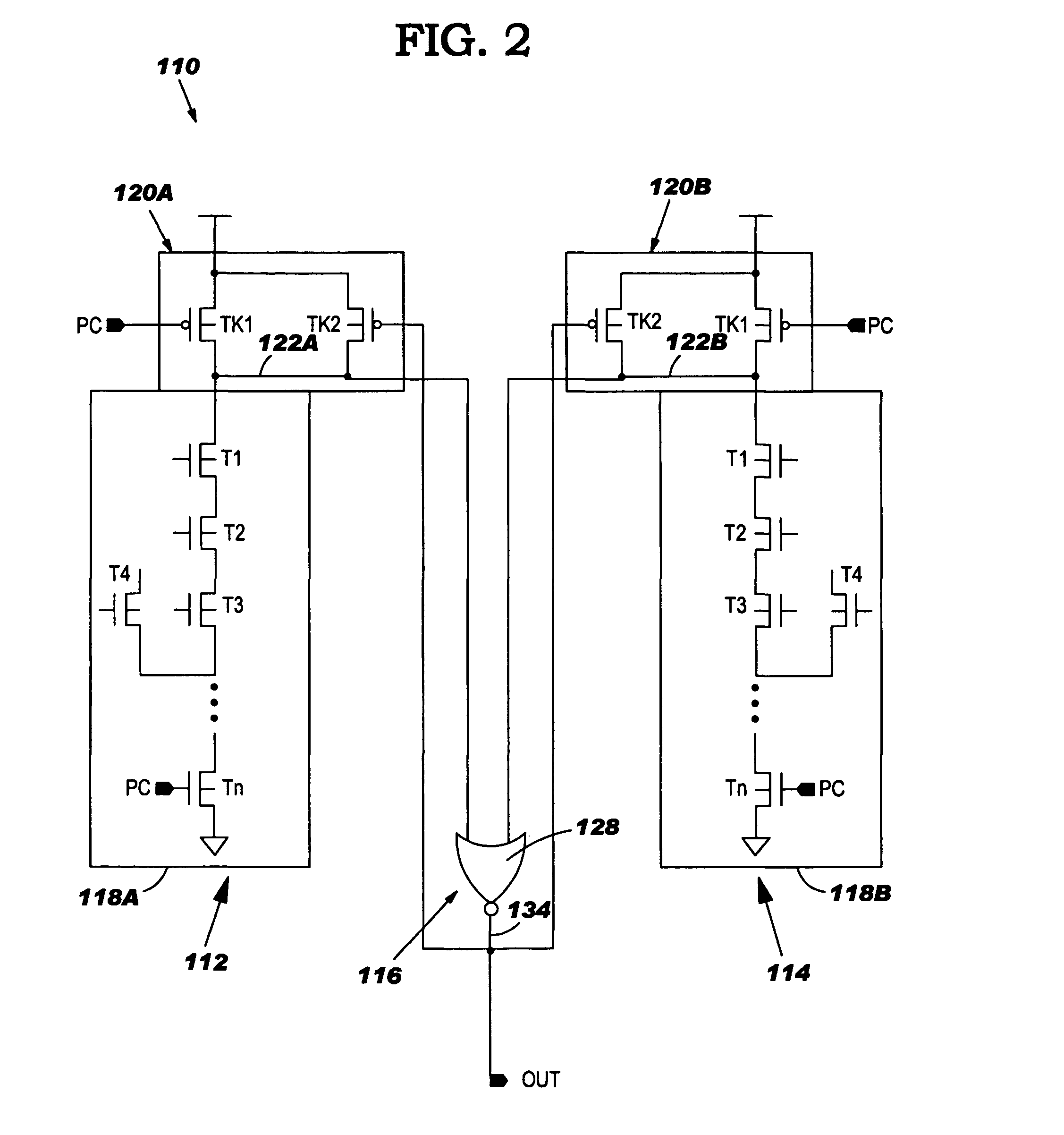
[0023] Referring to FIG. 2, an error correcting logic system 110 according to the invention is shown. System 110 includes a first DLG 112, a second DLG 114, which is identical to first DLG 112, and an interconnecting gate 116 connected to receive the outputs of both switches 112, 114. Each DLG 112, 114 includes a combinatorial logic section 118A, 118B and a pre-charge section 120A, 120B that are connected to form a critical node 122A, 122B, respectively. Again, DLG 112 and DLG 114 are each of a non-differential output type, and each critical node 122A, 122B is pre-charged HIGH. Further, it should be recognized that while two DLGs 112, 114 have been illustrated, the invention may include any number of DLGs 112, 114 feeding to interconnecting gate 116. Each critical node 122A, 122B is coupled to a respective input of interconnecting gate 116 in the form of a NOR gate 128. Combinatorial sections 118A, 118B and pre-charge sections 120A, 120B are substantially identical to those describe...
PUM
 Abstract
Description
Claims
Application Information