
Plant Support Fixture

Inactive Publication Date: 2006-02-09
PRAVETTONI ANGELICA
View PDF35 Cites 6 Cited by
  • Summary
  • Abstract
  • Description
  • Claims
  • Application Information

AI Technical Summary

Benefits of technology

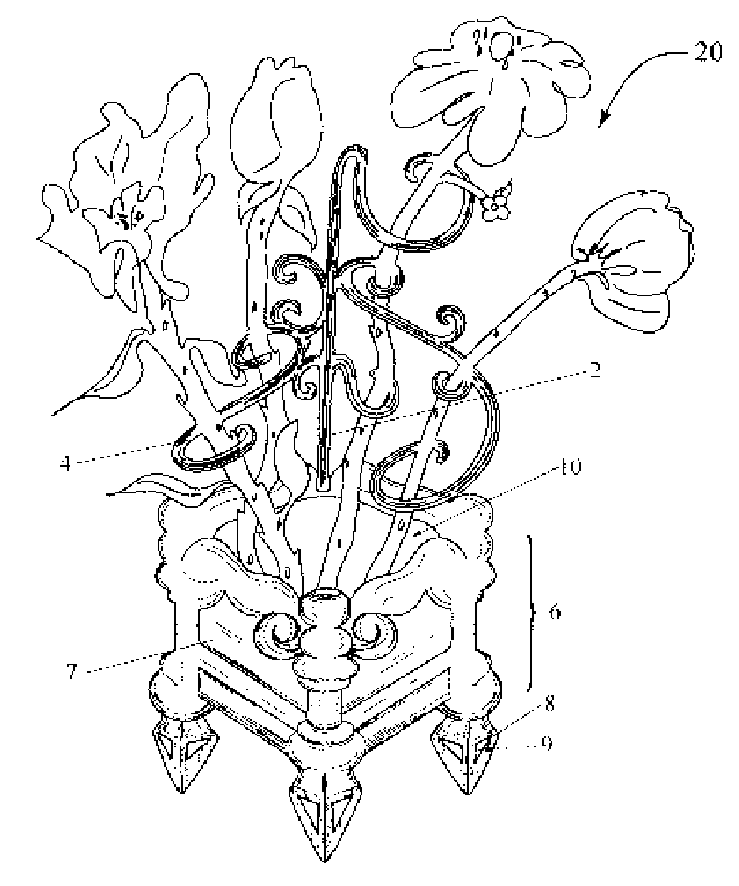
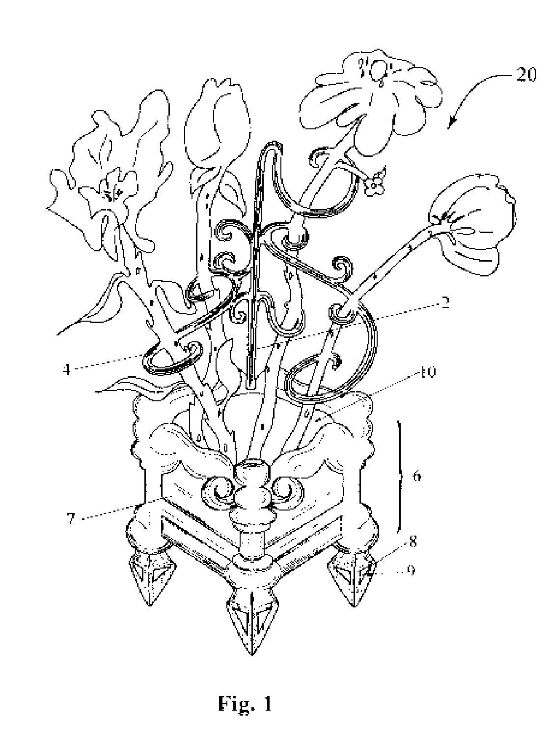
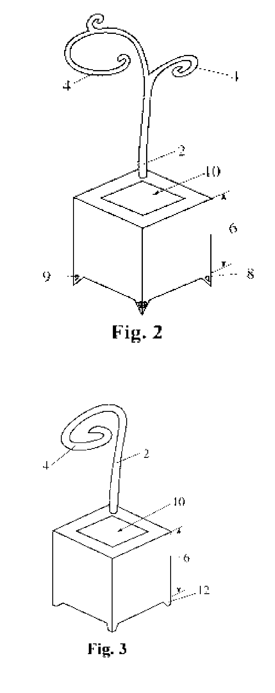
[0015] One or more support arm members may be attached to and may extend radially from the main support unit. The main support unit and the support arm members may be formed as a single unit or alternatively, the support arm members may be removeably attached to the main support unit. Depending on the complexity of the design, the plant support fixture may have one support arm member or more than one support arm member. The support arm members may extend away from the main support unit at various radial angles, such that the support arm members are fanned out in an array to allow for a number of flowers and plant stems to be supported. The support arm members may be of differing lengths and may attach to the main support unit at varying heights around the main support unit, so as to accommodate a variety of different flower and plant stems and to present them in an aesthetically pleasing manner. In addition, the support arm members may be formed into an open coil shape, which allows the flower and plant stems to be inserted into the support arm members easily and rapidly while being held into place without the need for extraneous string or twine ties. Moreover, the support arm members may be comprised of open coil shapes of varying outside diameters, so as to accommodate one or more flower or plant stems per support arm member or to accommodate flower or plant stems of varying diameters. The main support unit and the support arm members may be made from a variety of different materials including, but not limited to, steel, iron, or aluminum.
[0016] In accordance with another embodiment of the present invention, the plant support fixture may further comprise feet members attached to the bottom of the receptacle. The feet members may be removeably attached to the bottom of the receptacle, allowing different types of feet members to be interchanged with the same receptacle. In one embodiment of the present invention, the feet members may have a flat contact surface with the ground. A plant support fixture equipped with flat feet members is suitable for use either indoors or outdoors. In alternative embodiments, the feet members may have a contact surface with the ground that is spike-shaped. The spike-shaped, contact surface may taper to a substantially pointed tip. The spike-shaped feet members are configured to form into shapes such as, but not limited to, an inverted cone or an inverted pyramid, which are suitable for penetrating into soil, sand or grass. The spike-shaped feet members, may allow the plant support fixture to be securely anchored to the ground by pressing the fixture into the ground, such that the spike-shaped feet members penetrate the earth and become embedded into the ground. This provides stability to the plant support fixture when used outdoors on uneven surfaces.

Problems solved by technology

However, the use of stakes is unattractive due to the unnatural appearance of straight wooden or metal stakes embedded into the soil and the artificial, man-made look of having the stems of the plant fixed to the stake with string or twine.
In addition, the use of stakes is time consuming because securing the stems of the plant to the stake requires a significant amount of time and labor.
Furthermore, maintaining the stake system requires additional time and labor because the ties and stake may need to be repositioned or replaced periodically as the plant grows.
In addition, typical stake support systems are inherently poor at providing adequate support for plants.
The standard stake system is flawed because the stakes are only inserted into the soil near the base of the plant and are not attached to the base of the pot containing the plant, resulting in the plant not being fully supported.
Gravity causes the stakes to lose their vertical orientation due to gravity the stakes have a tendency to lose their vertical orientation, which in turn reduces the effectiveness of the support.
Wooden stakes also have a tendency to bend over time because wood deteriorates in the sun's ultraviolet rays and loses its structural integrity.
In addition, if a wooden stake is left in wet soil or water, then the wood will begin to swell and break down or rot, leaving the plant unsupported.
However, if the stake is made out of iron or steel, then it will have a tendency to rust after exposure to water, wet soil, or the atmosphere over extended periods of time, thus making the stakes look unappealing and potentially dangerous to handle.
An additional drawback to a conventional plant support system, such as a stake or trellis, is that it is unable to supply the needed water or soil to a freshly cut plant or a living plant with roots growing in a pot or receptacle.
With an arrangement as such, the support fixture functions only to support the plant and does not provide the plant with needed water or soil.
In addition, the support fixture does not provide any drainage channels in the pot or receptacle through which excess water can drain away from the roots of the plant.

Method used


Image

  • Plant Support Fixture
  • Plant Support Fixture
  • Plant Support Fixture

Examples


Embodiment Construction

[0028] The description above and below and the drawings of the present document focus on one or more preferred embodiments of the present invention and also describe some exemplary optional features and / or alternative embodiments. The description and drawings are for the purpose of illustration and not limitation. Those of ordinary skill in the art will recognize variations, modifications, and alternatives. Such variations, modifications, and alternatives are also within the scope of the present invention.

[0029] An embodiment of the present invention includes a decorative plant support fixture 20, as shown in FIG. 1. Decorative plant support fixture 20 is comprised of a decorative pot, planter, or receptacle 6 having a bottom and side walls 7, a main support unit 2, and one or more foliage and plant support arm members 4. The bottom and side walls 7 of receptacle 6 define the outer shape of receptacle 6 and also are configured to form an enclosed inner central cavity 10. Flowers an...


PUM


Abstract

A decorative plant support fixture having a receptacle for holding flower stems, plants, or other foliage. The support fixture has a main support unit, which may have one or more support arm members protruding from the main support unit at various heights and radial angles around the main support unit. Flowers and plants are supported by support arm members which may be coil shaped on one end, and of different sizes, so as to accommodate flowers and plants of different sizes and stages of growth. The plant support fixture may also include flat feet members for placing the fixture on any substantially flat indoor or outdoor surface. The plant support fixture may also include spike-shaped feet members which can penetrate the soil and anchor the fixture to the ground. Support fixture may also include an attachment means for securing fixture to any substantially vertical surface.

Description

CROSS-REFERENCE TO RELATED APPLICATION [0001] This application claims priority of U.S. Provisional Application No. 60 / 592,438 filed Jul. 30, 2004, which is incorporated herein by reference.BACKGROUND OF THE INVENTION [0002] This invention relates to a plant support system and, more particularly, a plant support fixture that provides support for potted plants as well as freshly cut, dried or artificial, flowers and plants. [0003] Plant support systems have been produced in the past. For example, one plant support system well known in the field involves the use of wooden or metal stakes. Long wooden or metal stakes are inserted into the ground near the base of the plant and the stems of the plant are tied to the stake with string or twine. However, the use of stakes is unattractive due to the unnatural appearance of straight wooden or metal stakes embedded into the soil and the artificial, man-made look of having the stems of the plant fixed to the stake with string or twine. In addit...

Claims


Application Information

Patent Timeline
IPC IPC(8): A47G7/00
CPCA47G7/07A01G9/12
Inventor PRAVETTONI, ANGELICA
Owner PRAVETTONI ANGELICA
Learn More