Apparatus for cooling a strip of sheet metal

a technology for sheet metal and cooling apparatus, which is applied in the direction of heat treatment apparatus, manufacturing tools, furniture, etc., can solve the problems of insufficient achievement, fluctuation in thickness over the width of the strip, and inability to preven

Inactive Publication Date: 2006-02-09
EBNER-INDUSTRIEOFENBAU GMBH
View PDF4 Cites 2 Cited by
  • Summary
  • Abstract
  • Description
  • Claims
  • Application Information

AI Technical Summary

Benefits of technology

[0005] The use of fan jet nozzles whose jets form a common middle spraying surface for each transversal row allows a substantially even distribution of the cooling liquid over the spraying surface, assuming a predetermined alignment of the jet which remains the same during the cooling relative to the bottom side of the strip, because the distribution of liquid which is uneven especially over the longitudinal extension of the spraying region of the individual fan jet nozzles can be offset sufficiently through a respective overlapping of the individual spraying regions. An additional factor is that as a result of the covers which are laterally adjacent to the strip and are in alignment with the bottom side of the strip it is possible to ensure a cooling meeting the conditions in the region between the longitudinal edges, because a wetting of the upper side of the strip in the region of the longitudinal boundary can be avoided which would occur otherwise due to unavoidable turbulent flows, so that the desired even cooling over the width of the strip can be ensured right up to the longitudinal boundary region.
[0006] Especially advantageous boundary conditions can be maintained when the covers are in alignment with the bottom side of the strip. The lateral covers in alignment with the bottom side of the strip form a spraying surface extending beyond the width of the strip which enables comparable reflection conditions for the sprayed cooling liquid beyond the edge of the strip.
[0007] In order to advantageously utilize the desired effect of lateral covers it is necessary to ensure a low distance between the longitudinal edges of the strip and the laterally adjacent covers. For this purpose, the covers can be displaced transversally to the feeding direction depending on the course of the longitudinal edge of the strip of sheet metal, which can be realized for example in a simple way from a constructional standpoint by scanning the longitudinal edges of the strip and a control device triggered by said scanning for the actuating drives of the covers.
[0008] The even sudden use of strip cooling must not be impaired by disturbing influences such as cooling liquid reflected from the housing walls. The same applies to the outlet region of the cooling section. In order to avoid such disturbing influences on the one hand and in order to secure a constructional limitation of the cooling section on the other hand, the spray region of the nozzles in the feeding direction of the strip can be limited by a deflection device for the cooling liquid which is provided beneath the strip of sheet metal. The portion of liquid sprayed by the closest transversal row of nozzles against the deflection device is diverted from the strip before it meets the lower side of the strip, which provides advantageous constructional conditions, especially when the nozzles of the transversal rows at the front and back in the feeding direction of the strip can be set in their inclination about an axis extending in the direction of the transversal row.

Problems solved by technology

This is achieved only insufficiently.
Since in the case of full jet nozzles, which are pressurized with cooling liquid below a preferred, comparatively low pressure of up to 1 bar, the central spraying region shows a high cooling effect, one must expect a shrinkage of the strip of sheet metal starting from these central spray regions, leading to fluctuations in the thickness over the width of the strip, which cannot be prevented even when the full jet nozzles combined in nozzle beams are moved in an oscillating fashion to and fro transversally to the feeding direction of the strip.
An additional factor is that in the longitudinal boundary region there is an inevitable different distribution of the sprayed cooling liquid as compared with the region situated in between, so that although it is possible to achieve a more even cooling with this known apparatus, the cooling is still insufficient to meet higher demands placed on a rapid and even cooling of the strip.

Method used


Image

  • Apparatus for cooling a strip of sheet metal
  • Apparatus for cooling a strip of sheet metal
  • Apparatus for cooling a strip of sheet metal

Examples


Embodiment Construction

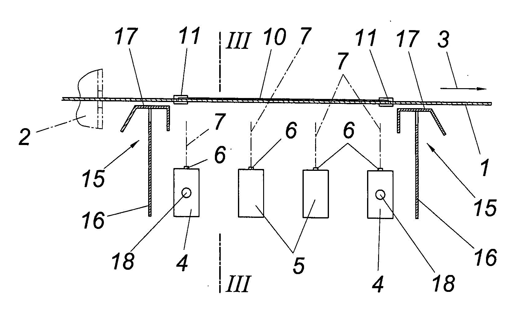
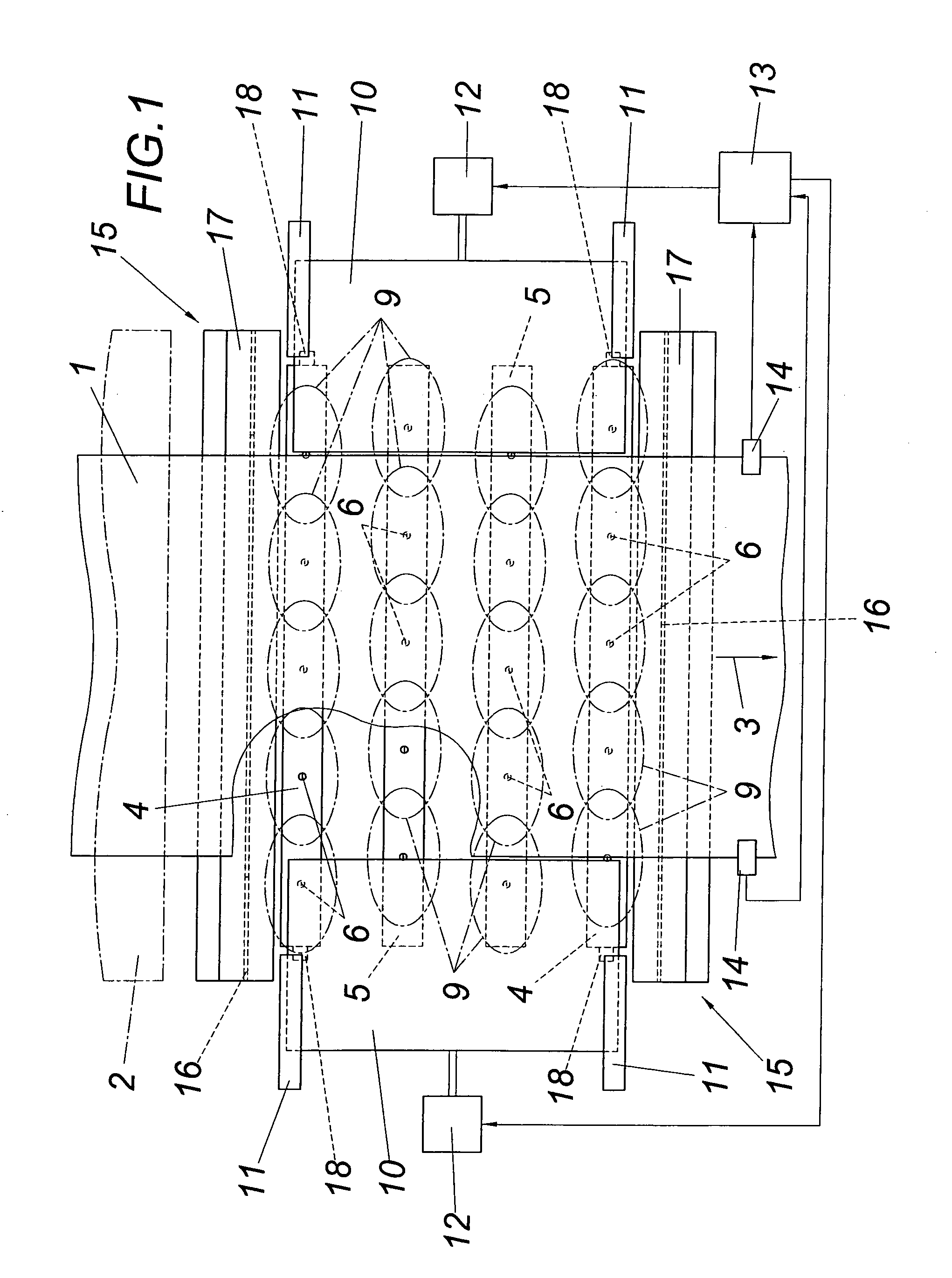
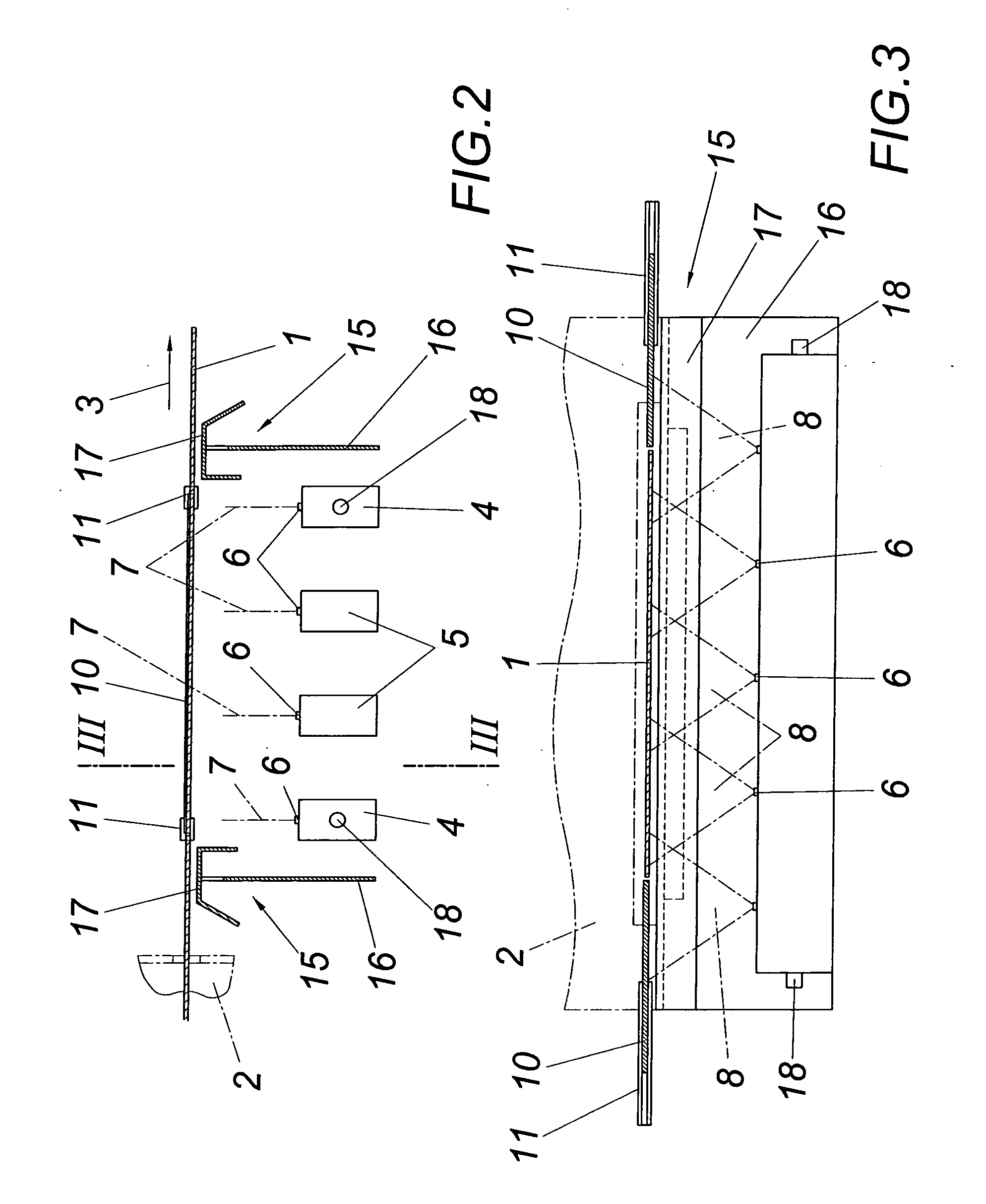
[0013] The illustrated apparatus for cooling a strip 1 of sheet metal which is conveyed out of a continuous furnace 2 with the help of a supporting air cushion comprises several spray beams 4 and 5 which extend transversally to the feeding direction 3 of the strip 1 of sheet metal and are situated beneath the strip 1 of sheet metal, with the nozzles 6 of the spray beams 4 and 5 configured as fan jet nozzles being arranged in mutually offset transversal rows, as is shown in FIG. 1. Within each transversal row, the nozzles each form a common middle spray surface 7, as is shown in FIG. 2 with the dot-dash line. This means that the spray cones 8 of the fan jet nozzles 6 which overlap one another in the region of the bottom side of the strip and are shown in dot-dash lines in FIG. 3 lead to a spray region 9 on the bottom side of the strip as indicated in FIG. 1 with the dot-dash line, which spray region, in cooperation with the spray regions of the other nozzles of a transversal row, ens...


PUM

PropertyMeasurementUnit
pressureaaaaaaaaaa
pressureaaaaaaaaaa
widthaaaaaaaaaa

Abstract

An apparatus is described for cooling a strip (1) of sheet metal with nozzles (6) for a cooling liquid to be sprayed onto the bottom side of the strip, which nozzles are arranged beneath the strip (1) in transversal rows relative to the feeding direction (3) of the strip. In order to provide advantageous cooling conditions it is proposed that the nozzles (6) configured as fan jet nozzles form a common middle spraying surface (7) for each transversal row and that covers (10) are provided in the spraying region of the nozzles (6) which are laterally adjacent to the strip (1) of sheet metal.

Description

1. FIELD OF THE INVENTION [0001] The invention relates to an apparatus for cooling a strip of sheet metal with nozzles for a cooling liquid to be sprayed onto the bottom side of the strip, which nozzles are arranged beneath the strip in transversal rows relative to the feeding direction of the same. 2. DESCRIPTION OF THE PRIOR ART [0002] For the purpose of rapidly cooling hot strips of sheet metal it is known (EP 0 695 590 A1) to spray a cooling liquid, especially water, against the bottom and upper side of the strip, which occurs with the help of jet nozzles which are arranged in longitudinal rows distributed over the width of the strip and extending in the feeding direction of the strip and, depending on each longitudinal row, are situated in a common median spraying surface. The fan jets of the nozzles aligned in the feeding direction of the strip are deflected in an alternating manner to both sides with the help of compressed air transversally to the feeding direction of the str...

Claims


Application Information

Patent Timeline
Patent Type & Authority Applications(United States)
IPC IPC(8): B05C5/00B05B7/00B05B7/06B05D1/02B21B45/02C21D1/667C21D9/573
CPCB21B45/0218B21B45/0233C21D9/5735C21D9/573C21D1/667
Inventor EBNER, PETER
Owner EBNER-INDUSTRIEOFENBAU GMBH
Why Eureka
Try Eureka