

Pressure-sensitive adhesive type optical film and image display
- Summary
- Abstract
- Description
- Claims
- Application Information
AI Technical Summary
Benefits of technology
Problems solved by technology
Method used
Image

Examples
example 1
(Production of an Optical Film)
[0089] After a polyvinyl alcohol film with a thickness of 80 μm was stretched 5 times in 40° C. iodine aqueous solution, it was dried for 4 minutes at 50° C. to obtain a polarizer. Triacetyl cellulose films were adhered on both sides of this polarizer through a polyvinyl alcohol based adhesive to obtain a polarizing plate.
(Formation of an anchor layer)
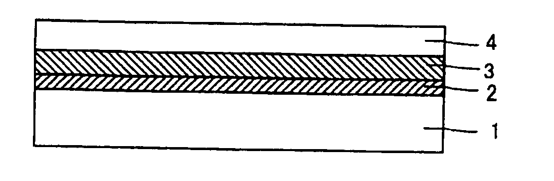
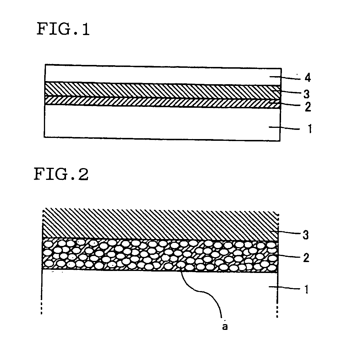
[0090] A solution diluted into 5% of a solid content was prepared by dissolving Adeka Bontighter HUX 290H (an emulsion mean particle diameter of about 42 nm) manufactured by Asahi Denka Co., Ltd., as a resin emulsion of a polyurethane, with a mixed solvent of water: butyl cellosolve=3: 1 (volume ratio). This solution was applied on the polarizing plate using a wire bar #5, and, subsequently volatile matter was evaporated off. Observation by a TEM ultrathin membrane section method of a thickness of the anchor layer after evaporated gave a thickness of 1000 nm, and showed that 6 to 7 emulsion particles...
example 2
(An Optical Film)
[0093] Corona treatment was given to a retardation plate (100 μm) using a biaxially stretched norbornene based resin (manufactured by JSR, Arton) (71° of an angle of contact with water), and the obtained plate was used.
(Formation of an Anchor Layer)
[0094] As a polyethylene imine addition product of acrylic / styrene based copolymer emulsion, POLYMENT SK-1000 (an emulsion mean particle diameter of about 100 nm) manufactured by NIPPON SHOKUBAI Co., Ltd. was dissolved with a mixed solvent of water:isopropyl alcohol=1:3 (volume ratio), to prepare a solution diluted into 5% of a solid content. After this solution was applied on the retardation plate using a wire bar #5, volatile matter was evaporated off. Observation by TEM ultrathin membrane section method of a thickness of the anchor layer after evaporated gave a thickness of 800 nm, and showed that 4 to 5 emulsion particles existed in a thickness direction.
(Production of a Pressure Sensitive Adhesive Optical Film...
example 3
(Production of an Optical Film)
[0096] A solution obtained by dissolving flakes of a polycarbonate (PC) in methylene chloride was uniformly cast a smooth SUS board, and the obtained board was dried in a solvent atmosphere so that the surface might not have dew formation. The obtained PC film was then removed from the SUS board after sufficient drying, and then dried in a circulating hot air type oven to obtain a non-stretched film of PC (30μ). This film was stretched by 1.2 times while being heated, and corona treatment was given to obtain a PC retardation plate (73° of an angle of contact with water).
(Formation of an Anchor Layer)
[0097] An anchor layer was formed on the PC retardation plate as in Example 2. Observation by a TEM ultrathin membrane section method of a thickness of the anchor layer after evaporated gave a thickness of 800 nm, and showed that 4 to 5 emulsion particles existed in a thickness direction.
(Production of a Pressure Sensitive Adhesive Optical Film)
[009...
PUM
| Property | Measurement | Unit |
|---|---|---|
| Thickness | aaaaa | aaaaa |
| Glass transition temperature | aaaaa | aaaaa |
| Thickness | aaaaa | aaaaa |
Abstract
Description
Claims
Application Information