Flat vibration brushless motor

a brushless, motor technology, applied in the direction of electrical transducers, dynamo-electric machines, structural associations, etc., can solve the problems of inability to miniaturize the magnetic sound transducer, achieve a low profile, and be durable enough for the speaker life, so as to prevent the problem of the motor rotation characteristics

Inactive Publication Date: 2006-02-09
TOKYO PARTS IND CO LTD
View PDF11 Cites 30 Cited by
  • Summary
  • Abstract
  • Description
  • Claims
  • Application Information

AI Technical Summary

Benefits of technology

[0012] It is an object of the present invention to prevent problems in motor rotation characteristics even when there is magnetic field leakage, thereby enabling use of the motor as a magnetic pole piece receiving an outside magnetic field.

Problems solved by technology

However, with such constitutions, a magnetic sound transducer cannot be miniaturized.
However, with such a constitution, because it is a cored type and a spindle is attached to an output shaft, it cannot achieve a low profile, and because it uses a brush commutator and a high-speed motor, it is not sufficiently durable for speaker life.
However, such a thin brushless motor entails troublesome issues when integrated into a magnetic sound transducer.
Therefore, when such a magnet is used with a single Hall sensor for reasons of disposition capacity, a detent generation member is adversely impacted, and there are start-up related problems.
As a result, magnetic field leakage easily occurs, and with a fixed yoke slotless type motor, in the space between the magnetic portions of housing constituted by case and bracket, there is main magnetic field absorption loss as well as absorption loss due to the magnetic field leakage.

Method used


Image

  • Flat vibration brushless motor
  • Flat vibration brushless motor
  • Flat vibration brushless motor

Examples


embodiment 1

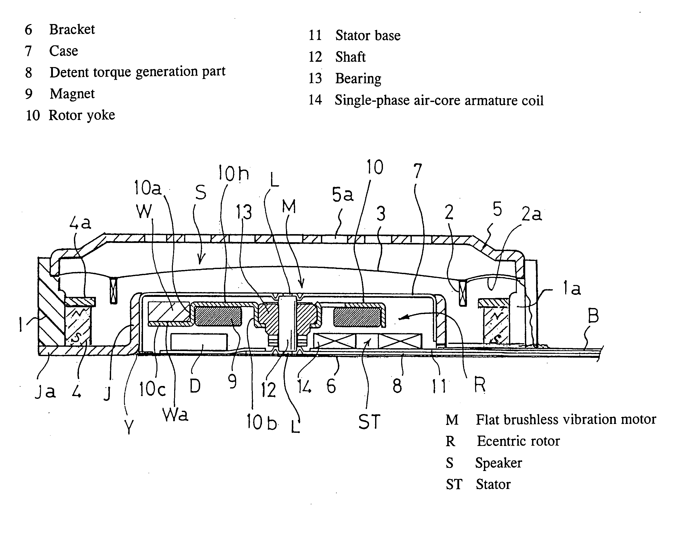
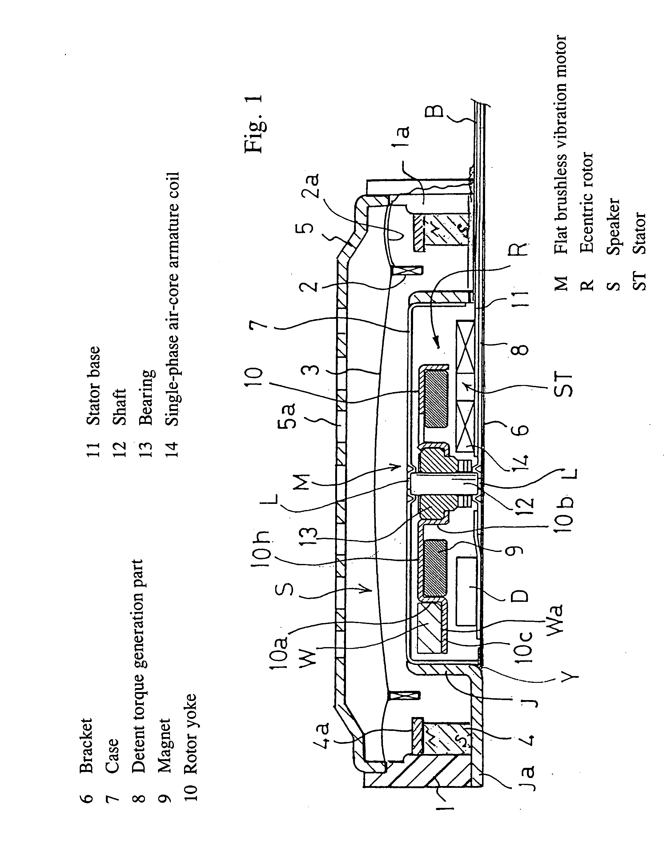
[0042] A magnetic sound transducer S containing a flat brushless vibration motor constituting the present invention comprises a speaker housing 1 in the form of a shallow cylinder made of resin, a flat vibration motor M disposed in the center thereof and having an eccentric rotor incorporated therein, a ring-shaped moving voice coil 2 caused to face a radial outer periphery of the motor across a gap and formed as a multilayer solenoid type, a film-like diaphragm 3 made of a synthetic resin to which one end of the coil is attached and the outer periphery of which is attached to the housing, and a ring-shaped excitation magnet 4 disposed in the housing across a gap with respect to the outer periphery of the moving voice coil 2. A terminal 2a of the moving voice coil 2 is made to conform to the diaphragm 3 by adhesion or the like, and is led to a feed terminal part B across a partial space 1a in the speaker housing 1 lateral surface.

[0043] These members are respectively covered with a...

embodiment 2

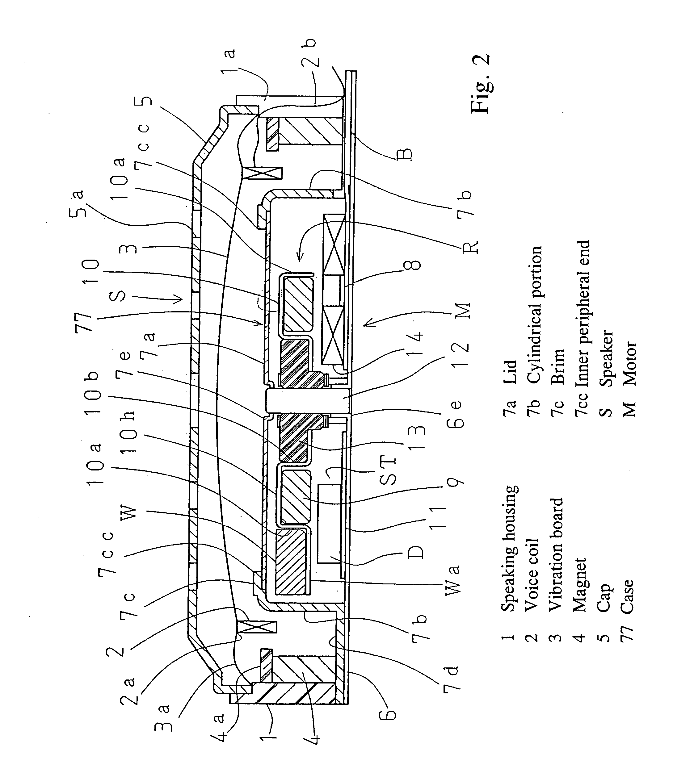
[0057] In the second embodiment illustrated in FIG. 2, a constitution of a magnetic sound transducer S is identical to that of the above described embodiment 1, which identical members, including a brushless vibration motor M, are given the same reference symbols and explanation thereof is omitted.

[0058] This flat brushless motor M is characterized in that a case 77 is different from that of the above embodiment. This case 77 comprises a tube 7b formed of a magnetic material in a cylindrical shape and a flange 7d formed continuously from the bottom of the tube 7b, and an outer periphery section of the flange 7d is fixed on the bottom end of the speaker housing 1. The excitation magnet 4 is attached to the speaker housing 1 and flange 7d.

[0059] The case 77 is constituted such that a lateral periphery portion thereof, together with the excitation magnet 4 and yoke plate 4a, forms a magnetic path for speaker that acts on the voice coil 2; it also serves as housing for the brushless m...

embodiment 3

[0066]FIG. 3 illustrates a third embodiment, in which magnetic balance is attained on the eccentric rotor. Here too, members identical to those of the above described embodiments are given the same reference symbols and explanation thereof is omitted.

[0067] The flat brushless vibration motor M constituting the present invention comprises a Hall sensor type single-phase brushless motor. As is well-known, for purposes of automatic start, a single-phase brushless motor needs to have a rotor stop at a prescribed position. However, when a magnetic body is used for the bracket 6 and case 7, the magnetic force of the large magnet renders start difficult, and for this reason a large gap is required. Normally, however, to reduce the motor size, the bracket 6 needs to be a nonmagnetic body except for the detent torque generation part 8. When a motor with thickness of about 2 mm is used, the rotor yoke 10 holding a magnet also must be thin, meaning that above, on the side opposite the gap, fl...


PUM


Abstract

An eccentric rotor rotatably accommodated via a shaft in a housing at least one part of which is made nonmagnetic or weakly magnetic comprises a rotor case, an axial air-gap magnet held in the rotor case, a nonmagnetic eccentric weight fixed on the rotor case outward of the magnet, and a bearing support disposed on the rotor case inward of the magnet, and a stator disposed on a portion of the housing and driving the eccentric rotor across an axial gap comprises a shaft support portion provided in the center, a bracket having a detent torque generation part formed of a magnetic body disposed on a periphery of the shaft support portion, at least two air-core armature coils wired in a single-phase and provided in a stator base attached to the bracket, a drive circuit member disposed so as not to overlap with the air-core armature coils and supplying electric to the air-core armature coils, and a feed terminal to be connected to the drive circuit member.

Description

TECHNICAL FIELD [0001] The present invention relates to a flat brushless vibration motor suitable for silent alarm means; more specifically, it relates to a flat vibration motor used as a single unit or incorporated in a magnetic sound transducer (commonly known as a micro speaker) or the like tand configured as a central magnetic pole. BACKGROUND ART [0002] Conventionally, as a flat brushless vibration motor comprising an eccentric rotor, a fixed yoke type used as an axial air-gap slotless type is known. See Japanese Utility Model Registration 2549357. [0003] Also, there is a magnetic sound transducer such that a pair of plate-shaped elastic bodies are supported by a frame body so as to oppose each other, a magnetic field generator comprising a yoke and magnet is attached to one plate-shaped elastic body, a ring-shaped moving voice coil is attached to the other plate-shaped elastic body, the coil is disposed within the magnetic field of the magnetic field generator, and currents wi...

Claims


Application Information

Patent Timeline
Patent Type & Authority Applications(United States)
IPC IPC(8): H02K7/06
CPCH02K7/063H02K11/0073H02K11/0005H02K11/33H02K11/0141H04R9/02
Inventor YAMAGUCHI, TADAOOSAKI, TAKESHIFUJII, KENTAROKOYANAGI, NAOHISA
Owner TOKYO PARTS IND CO LTD
Why Eureka
Try Eureka