Method and apparatus for measuring formation conductivities from within cased wellbores by combined measurement of casing current leakage and electromagnetic response

a technology of electromagnetic response and conductivity measurement, which is applied in the direction of measurement devices, instruments, scientific instruments, etc., can solve the problems of difficult to use conventional (so called “open hole”) techniques to determine the resistivity of various earth formations from within steel pipes or casings, and the measurement of formations of interest penetrated by a typical wellbore takes an extensive amount of time, so as to achieve slow movement of the measurement apparatus and measure the resistivity of the earth formations

Active Publication Date: 2006-02-09
KJT ENTPR
View PDF29 Cites 73 Cited by
  • Summary
  • Abstract
  • Description
  • Claims
  • Application Information

AI Technical Summary

Benefits of technology

[0021] The method includes measuring resistivity of the Earth formations using measurements of current leakage along the pipe at selected axial positions. Electromagnetic properties of the Earth formations are measured from within the pipe. The measurements of electromagnetic properties correspond to a larger axial distance and to a greater lateral distance than the measurements of resistivity from current leakage. The current leakage and electromagnetic measurements are jointly inverted to obtain a model of the spatial distribution. The combination enables a slow moving of the measurement apparatus.

Problems solved by technology

Steel casing is highly electrically conductive, and as a result makes it difficult to use conventional (so called “open hole”) techniques to determine the resistivity of the various Earth formations from within a steel pipe or casing.
The '196 patent does not disclose any technique for correcting the measurements for electrical inhomogeneities in the casing.
In practice, instruments and methods known in the art require that the instrument make its measurements from a fixed position within the wellbore, which makes measuring formations of interest penetrated by a typical wellbore take an extensive amount of time.
Further, the voltage drops being measured are small, and thus subject to noise limitations of the electronic systems used to make the measurements of voltage drop.
Still further, systems known in the art for providing no-current zones, or known current flow values for measurements of voltage drop, are typically analog systems, and thus subject to the accuracy limitations of such analog systems.
It is also known in the art to use polarity-switched DC to make through casing resistivity measurements, which avoids the polarization problem, but may induce transient effect error in the measurements when the DC polarity is switched.
Transient effects, and low frequency AC errors are not easily accounted for using systems known in the art.
While the method of the '458 patent is effective, it can be computationally intensive to perform, because voltage measurements from the resistivity measurement systems known in the art for measuring resistivity from within a conductive casing are extremely complex, and the number of possible Earth models which can be consistent with the measured response may cause initializing the Earth model to be time consuming.

Method used


Image

  • Method and apparatus for measuring formation conductivities from within cased wellbores by combined measurement of casing current leakage and electromagnetic response
  • Method and apparatus for measuring formation conductivities from within cased wellbores by combined measurement of casing current leakage and electromagnetic response
  • Method and apparatus for measuring formation conductivities from within cased wellbores by combined measurement of casing current leakage and electromagnetic response

Examples


Embodiment Construction

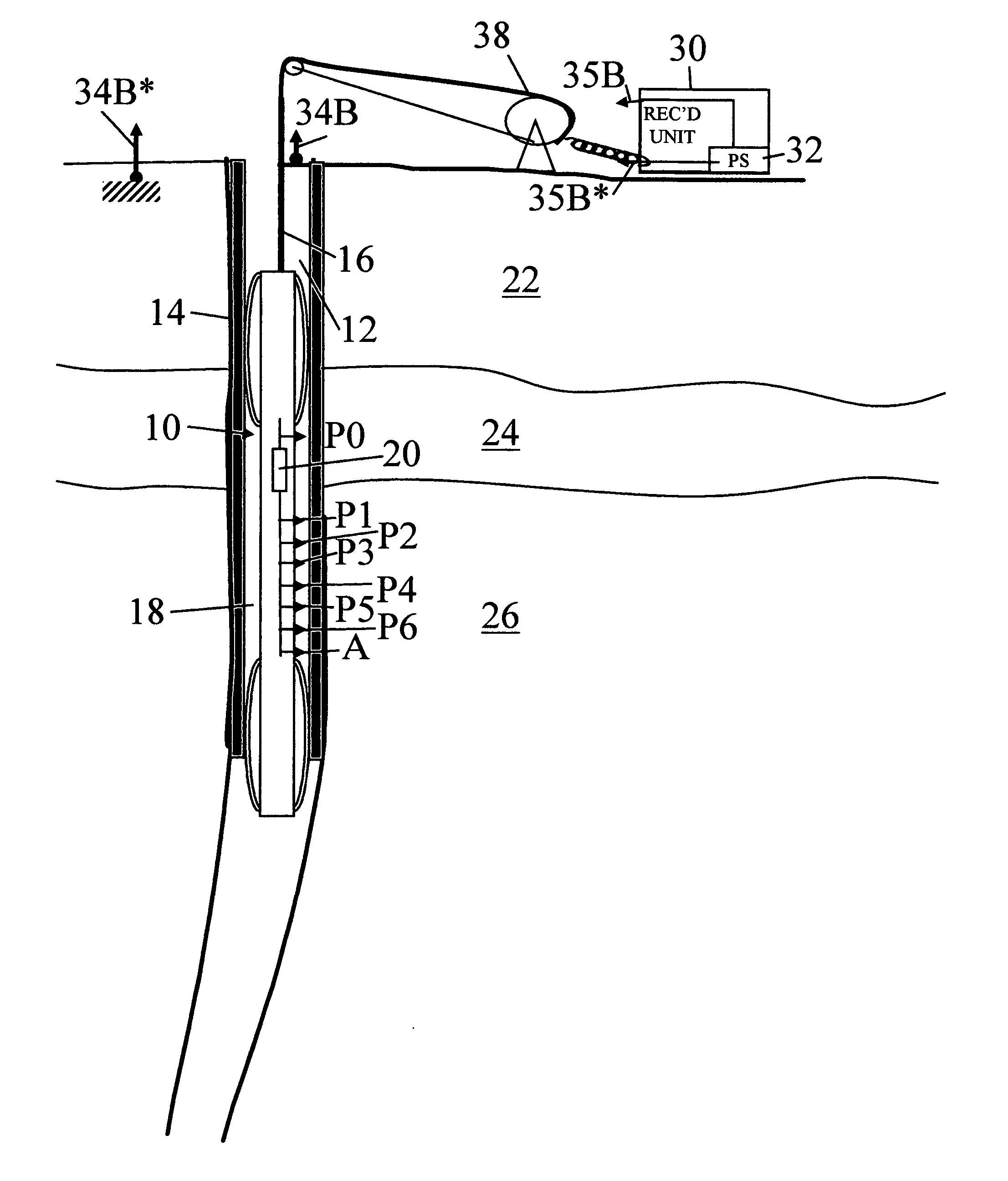
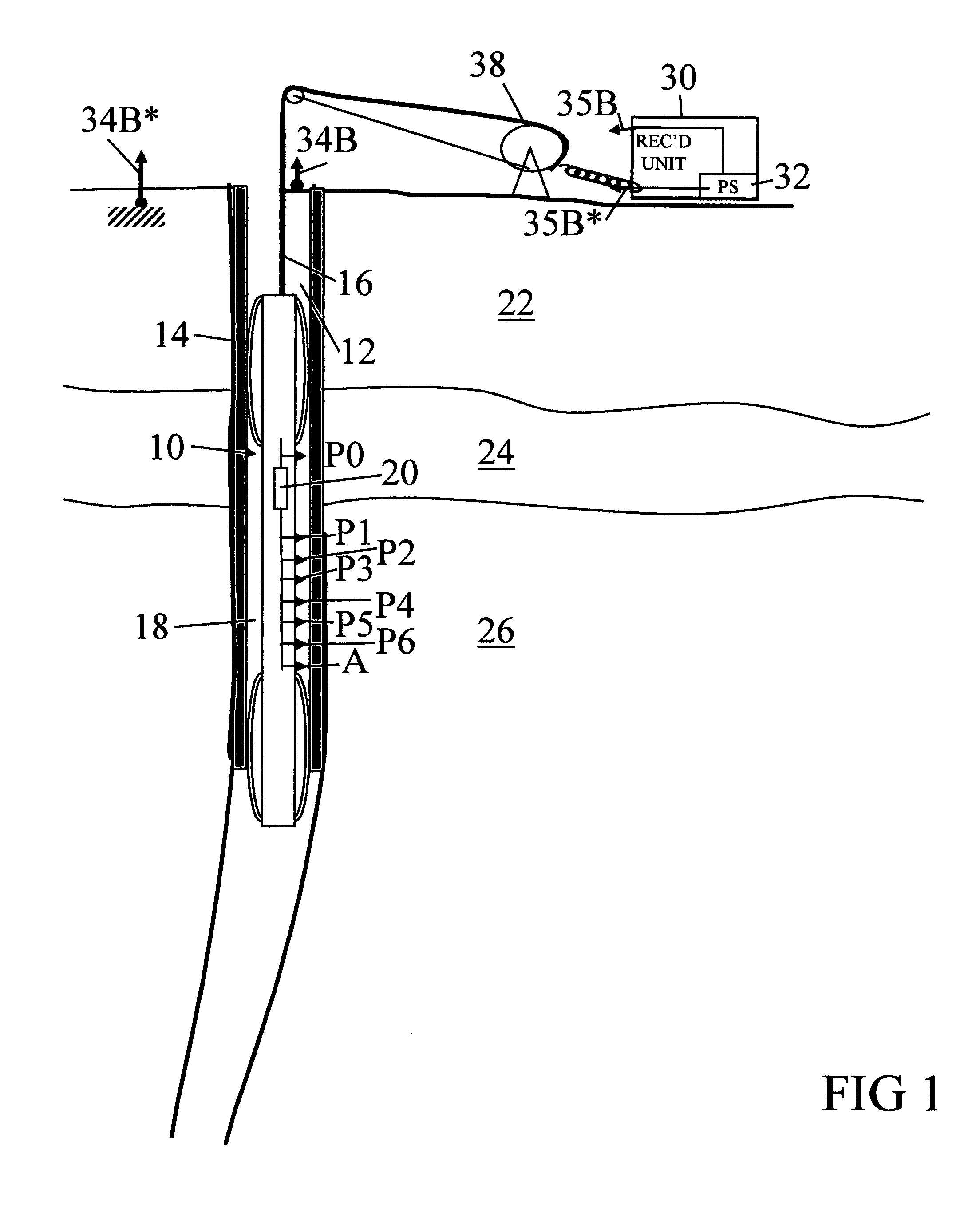
[0033] One embodiment of a well logging instrument used to measure resistivity of Earth formations from within a wellbore 14, when the wellbore has a conductive pipe or casing within, is shown schematically in FIG. 1. The instrument 10 may include a sonde or similar mandrel-type housing 18. The housing 18 is preferably made from an electrically non-conductive material, or has such non-conductive material on its exterior surface. The housing 18 is adapted to be inserted into and withdrawn from the wellbore 14, by means of any well logging instrument conveyance known in the art. In the present example, the conveyance can be an armored electrical cable 16, extended and retracted by a winch 38.

[0034] Other conveyances known in the art may be used, including coiled tubing, drill pipe, production tubing, etc. Accordingly, the conveyance is not a limit to the scope of the invention.

[0035] The wellbore 14 is drilled through various Earth formations, shown schematically at 22, 24 and 26. T...


PUM


Abstract

A method is disclosed for determining spatial distribution of resistivity of Earth formations surrounding a wellbore having a conductive pipe therein. The method includes measuring resistivity of the Earth formations using measurements of current leakage along the pipe at selected axial positions. Electromagnetic properties of the Earth formations are measured from within the pipe. The measurements of electromagnetic properties correspond to a larger axial distance and to a greater lateral distance than the measurements of resistivity from current leakage. The current leakage and electromagnetic measurements are jointly inverted to obtain a model of the spatial distribution.

Description

CROSS-REFERENCE TO RELATED APPLICATIONS [0001] Not applicable. STATEMENT REGARDING FEDERALLY SPONSORED RESEARCH OR DEVELOPMENT [0002] Not applicable. BACKGROUND OF INVENTION [0003] 1. Field of the Invention [0004] The invention relates generally to the field of Earth formation electrical resistivity measuring devices. More particularly, the invention relates to wellbore instruments for measuring formation resistivity from within an electrically conductive pipe or casing including a moving while measuring apparatus and method. [0005] 2. Background Art [0006] Electrical resistivity measurements of Earth formations are known in the art for determining properties of the measured Earth formations. Properties of interest include the fluid content of the pore spaces of the Earth formations. Wellbore resistivity measuring devices known in the art typically require that the Earth formations be exposed by drilling a wellbore therethrough, and that such formations remain exposed to the wellbor...

Claims


Application Information

Patent Timeline
Patent Type & Authority Applications(United States)
IPC IPC(8): G01V3/02
CPCG01V3/24
Inventor STRACK, KURT M.RUETER, HORST
Owner KJT ENTPR
Why Eureka
Try Eureka