Digital duty cycle corrector for multi-phase clock application

a technology of multi-phase clocks and correctors, applied in pulse manipulation, pulse techniques, instruments, etc., can solve the problems of difficult application of methods to applications in which a ready mode is available, difficult operation of methods at a high frequency, and difficulty in coercing a duty cycle with respect to a high speed clock

Inactive Publication Date: 2006-02-09
POSTECH CO LTD
View PDF7 Cites 14 Cited by
  • Summary
  • Abstract
  • Description
  • Claims
  • Application Information

AI Technical Summary

Problems solved by technology

However, since the method is characteristically sensitive to a change in temperature, process, and voltage according to the configuration of an analog circuit.
Since the inclination of a rising portion and a falling portion of an input clock must be gentle for accurate operation, coercing a duty cycle is with respect to a high speed clock is difficult.
Thus, according to the above method, the duty cycle of an input clock must be over 40% because a range of an adjustable offset voltage is limited and a range of change of the inclination of the rising portion and the falling portion of the input clock is limited.
However, since the amount of delay is still controlled by using an analog voltage, the method is sensitive to the change in temperature, voltage, and process and the method is difficult to be applied to an application in which a ready mode is needed.
Furthermore, since the pulse shapers 140 and 145 are used at an input end of the pulse width detector 150 to decrease the pulse width, the method is difficult to operate at a high frequency.

Method used


Image

  • Digital duty cycle corrector for multi-phase clock application
  • Digital duty cycle corrector for multi-phase clock application
  • Digital duty cycle corrector for multi-phase clock application

Examples


Embodiment Construction

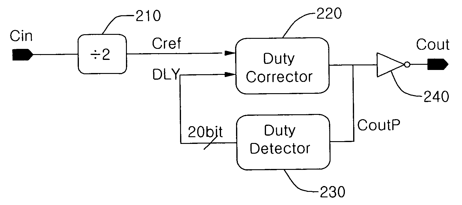
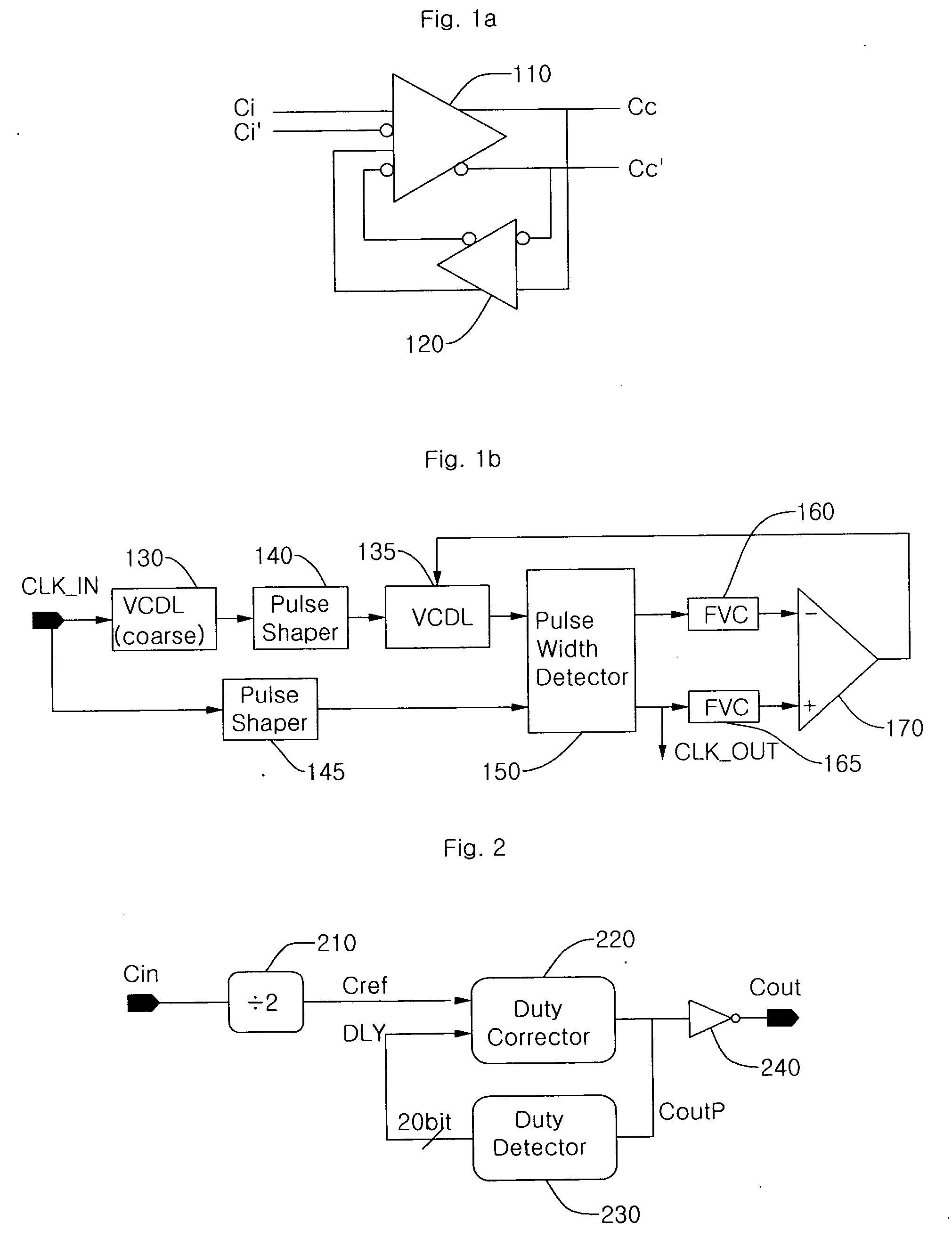
[0031]FIG. 2 is a block diagram of a digital duty cycle corrector according to an embodiment of the present invention. Referring to FIG. 2, the digital duty cycle corrector includes a toggle flip-flop 210, a duty corrector 220, a duty detector 230, and a phase inverter 240.

[0032] The toggle flip-flop 210 receives an input clock Cin having a cycle T and generates a reference clock Cref having a cycle 2T. Since the reference clock Cref is an output of the toggle flip-flop 210, when setup time and hold time of a flip-flop are secured, correction of duty is possible regardless of a duty cycle of the input clock Cin.

[0033] The duty corrector 220 receives the reference clock Cref having a cycle 2T as an input and generates an output clock CoutP having a cycle T. The duty cycle of the output clock CoutP is determined by a DLY value that is a 20-bit thermometer code which is another input to the duty corrector 220. When the DLY value increases, the duty cycle of the output clock CoutP dec...


PUM


Abstract

Provided is a digital duty cycle corrector for a multi-phase clock application which includes a flip-flop receiving a signal having a first clock cycle as an input and generating a reference signal having a cycle twice the first clock cycle, a duty corrector generating a signal having a second clock cycle that is half the cycle of the reference signal, from the reference signal, a duty detector measuring an amount of a duty error of the second clock cycle signal and generating a digital code value to control a duty cycle of the second clock cycle signal becomes 50%, and a phase inverter inverting a phase of the second clock cycle signal by 180° such that a rising edge of the second clock cycle signal is always fixed constantly regardless of a duty cycle correction operation.

Description

BACKGROUND OF THE INVENTION [0001] 1. Field of the Invention [0002] The present invention relates to a duty clock of a clock, and more particularly, to a duty cycle corrector of an internally generated clock. [0003] 2. Description of the Related Art [0004] Since all blocks of a duty cycle corrector can be embodied with digital logic, operation characteristics of the duty cycle corrector with respect to changes in operating temperature, process, and power voltage are superior and a correction to distortion of an input clock duty in a wide range is possible. Since phase information between multi-phase clocks is constantly maintained, an application of the duty cycle corrector to a system needing the multi-phase clock is possible. Also, since the duty information is stored as a digital code value, a quick switch from a ready mode to a normal operation mode is possible. [0005] In an SDRAM (DDR-SDRAM) using both rising edge and falling edge of a clock and circuits such as a MUX / DEMUX for...

Claims


Application Information

Patent Timeline
Patent Type & Authority Applications(United States)
IPC IPC(8): H03K3/017
CPCH03K5/1565H03L7/0814H03L7/0807H03L7/0805G11C7/222G11C11/4076
Inventor NAM, JANG JINPARK, HONG JUNE
Owner POSTECH CO LTD
Why Eureka
Try Eureka