Image controller

a mouse-type controller and image technology, applied in the field of image controllers, can solve the problems of increased manufacturing cost, affecting the desirability and value of items, and cost of manufacture ultimately affecting the desirability and value of items, and achieve the effect of great ease of us

Inactive Publication Date: 2006-02-09
ANASCAPE
View PDF99 Cites 24 Cited by
  • Summary
  • Abstract
  • Description
  • Claims
  • Application Information

AI Technical Summary

Benefits of technology

[0033] In order that 6 DOF controllers be more affordable, and for a user to be easily able to control objects and / or navigate a viewpoint within a three-dimensional graphics display, I have developed improved, low-cost hand operated 6 DOF controllers for use with a computer or computerized television or the like host device. The controllers provide structuring for converting full six degrees of freedom physical input provided by a human hand on a hand operable single input member into representative outputs or signals useful either directly or indirectly for controlling or assisting in controlling graphic image displays. The present controllers sense hand inputs on the input member via movement or force influenced sensors, and send information describing rotation or rotational force of the hand operable input member in either direction about three mutually perpendicular bi-directional axes herein referred to as yaw, pitch and roll, (or first, second and third); and information describing linear moment of the hand operable input member along the axes to a host computer or like graphics generation device for control of graphics of a display, thus six degrees of freedom of movement or force against the input member are converted to input-representative signals for control of graphics images.
[0053] Another object of the invention is to provide and meet the aforementioned objects in a six degree of freedom controller providing the advantage of versatility of complex movements wherein all three perpendicular Cartesian coordinates (three mutually perpendicular axes herein referred to as yaw, pitch and roll) are interpreted bi-directionally, both in a linear fashion as in movement along or force down any axis, and a rotational fashion as in rotation or force about any axis. These linear and rotational interpretations can be combined in every possible way to describe every possible interpretation of three dimensions.

Problems solved by technology

Thus, cost of manufacture ultimately influences the desirability and value of an item to the public at large.
Generally, physical-to-electrical converters embodied in hand operated electronic image controllers such as trackballs, mouse type and joystick type, increase in manufacturing cost as the number of degrees of freedom which can be interpreted between a hand operable input member and a reference member increase.
Likewise, a three or more degree of freedom mouse-type controller costs more to manufacture than a standard two degree of freedom mouse.
Manufacturing costs in such devices generally increase because, for at least one reason, an increasing number of sensors is necessary for the additional axes control, and the sensors in the prior art, particularly with 6 DOF controllers having a single input member, typically have been positioned in widely-spread three dimensional constellations within the controller, thus requiring multiple sensor mounts and mount locations and labor intensive, thus costly, hand wiring with individually insulated wires from the sensors to a normally centralized circuitry location remote from the sensors.
The prior art fails to provide structuring, such as a carriage member, for allowing cooperative interaction with sensors.
The prior art fails to demonstrate a carriage member which typically carries a sheet member connecting and supporting sensors.
Another failure in prior art 6 DOF controllers of the type having a hand operable single input member is the failure to use or anticipate use of inexpensive, flexible membrane sensor sheets, which are initially flat when manufactured, and which include sensors and conductive traces applied to the flat sheet structure.
Such “scattered”, individual sensor and sensor unit mounting locations are required in the King controller due to the failure to provide the structures for cooperative interaction with the sensors to all be located or brought into a single area of the controller, and thus the sensors in the King controller are not arranged in a manner allowing conventional automated installation such as on a generally flat circuit board, or for printed circuit traces engaging or connecting the sensors to be utilized, such as on a circuit board.
King also fails to anticipate the use of flexible membrane sensor sheets which include sensors and printed conductive traces which can be manufactured inexpensively in a flat sheet form, and used in flat sheet form, or alternatively, bent into three dimensionally formed shapes to position the sensors in three dimensional constellations.
Such structuring as in the King device is costly to manufacture, which accounts for, at least in part, why 6 DOF controllers are very costly when compared to two degree of freedom controllers.
Another problem in prior art controllers such as the King device is reliability.
In the King device, reliability is less than optimum due to the typical single input member 6 DOF prior art configuration of circuitry and sensors, because the hand wiring of sensors to remote circuitry is subject to malfunctions such as wires breaking, cold solder joints, and cross wiring due to error of the human assembler, etc.
Another problem in the circuitry and sensors as configured in typical prior art controllers, particularly 6 DOF controllers such as that of King, is serviceability, testing, and quality control during manufacturing, such as at the manufacturing plant wherein testing is applied before shipping, or after sales to the consumer such as with returns of defective controllers.
The typical widely-spread prior art sensor mounting and hand applied wiring associated with the sensors renders trouble shooting and repair more costly.
However, as will become appreciated, in Chang's controller, the lack of a hand operable single input member operable in six degrees of freedom has many significant disadvantages.
Further, the Chang controller does not have a any input member capable of being manipulated in 6 DOF relative to any reference member of the controller, which yields additional significant disadvantages.
Additionally, substantial physical space is required on a desk or table on which to propel a mouse type controller.
Another disadvantage of the Chang controller is that it is believed to be difficult to use, or in other words, the mouse roller ball on the underside of the housing which inputs linear moment information in some directions, is not capable of inputs in all linear directions, and thus the Chang device includes the thumb wheel off to the housing side which is utilized to emulate, approximate or represent linear movement along the third axis.
The hand movements required to move linearly utilizing pushing of the mouse housing for some directions, and the actuation of the thumb wheel for other directions is not intuitive and is thus confusing and difficult for the user.
Further, a mouse type controller such as Chang's cannot provide the desirable aspect of automatic return-to-center along the linear axes, or in other words, with a mouse, the user must actively move the mouse back to center (and center is often not easily determined by the user) since there are no feasible arrangements for the use of return-to-center springs or resilient structuring.
Additionally, the Chang device appears relatively expensive to manufacture, for at least one reason due to the use of six rotary encoders, three of which are utilized for linear inputs.
Rotary encoders are relatively expensive compared to many other sensor types.
Compared to some other types of sensors, rotary encoders are not only more expensive, but have significant disadvantages as linear input sensors.
Thus, the Chang device is functionally and structurally deficient.

Method used


Image

  • Image controller
  • Image controller
  • Image controller

Examples


embodiment 9

[0103] Referring now to the drawings in general, and particularly to drawing FIGS. 1 through 11 for a description a trackball-type embodiment 9 exemplifying principles of the invention. Joystick-type embodiments further exemplifying the principles of the invention are then described as additional preferred embodiments of the invention.

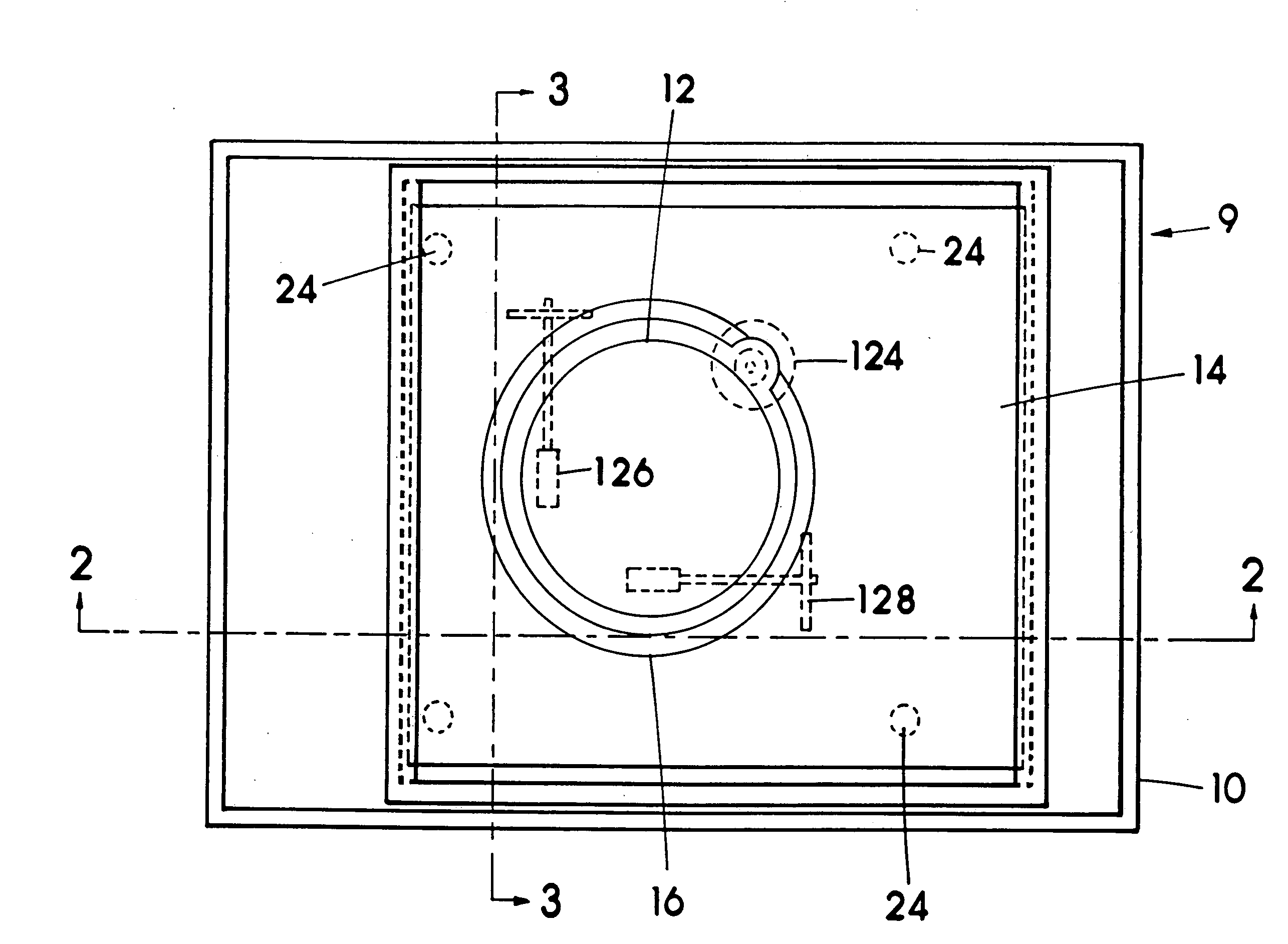
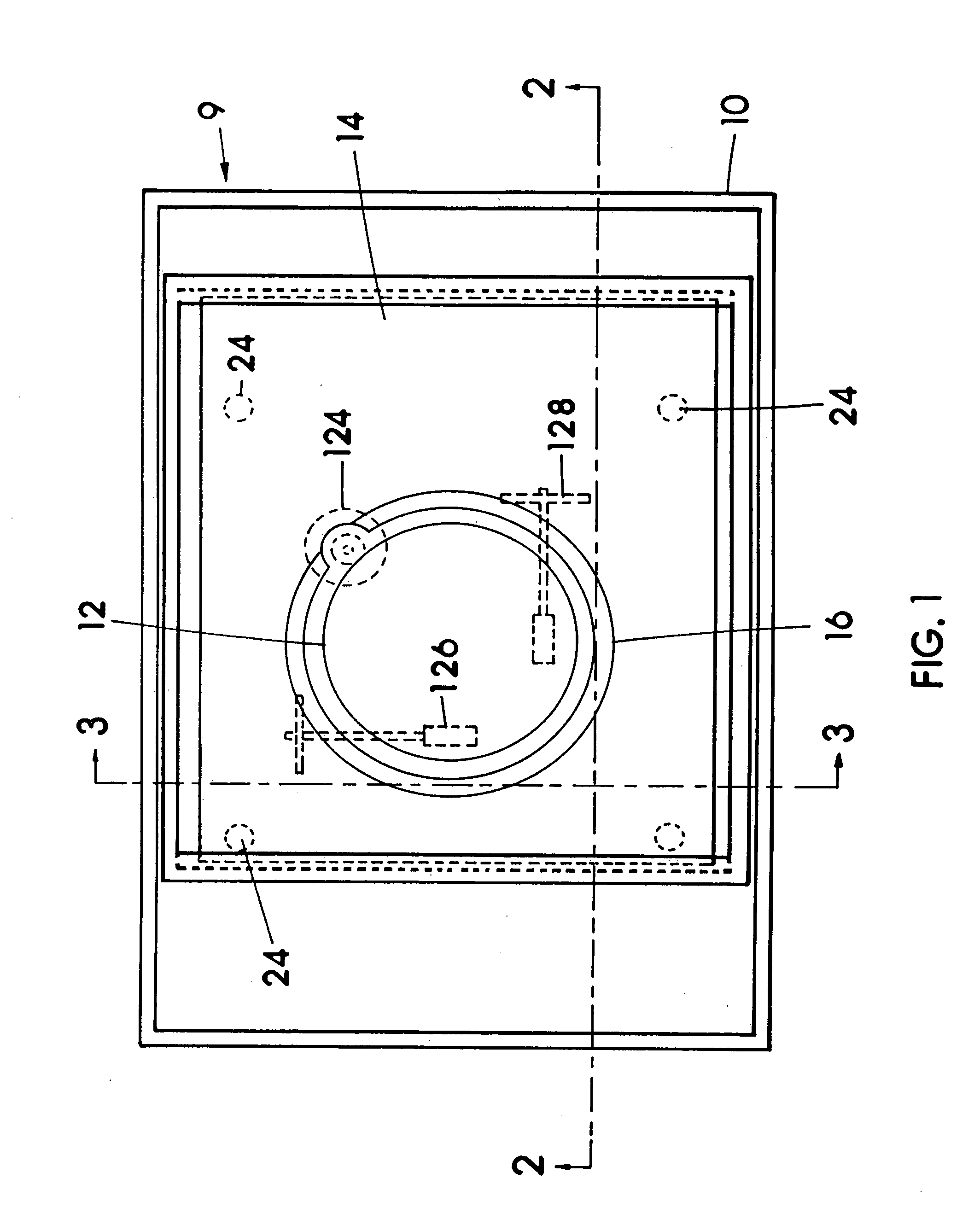
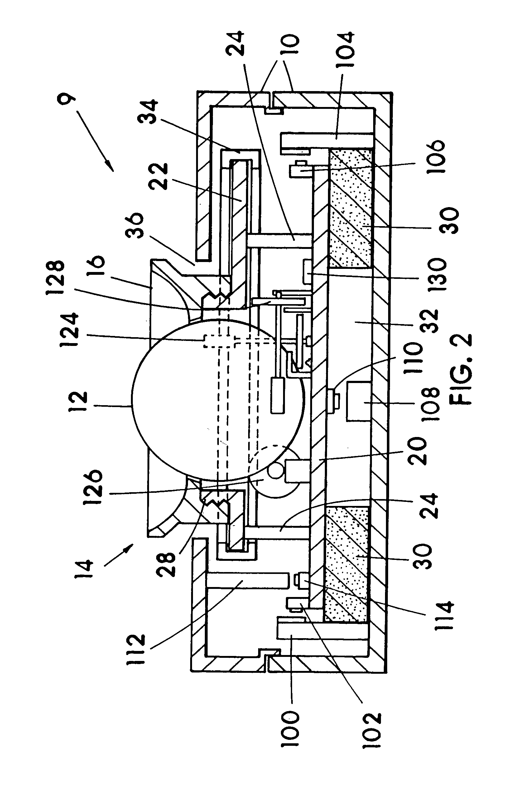
[0104] With reference to FIGS. 1-4 in particular wherein trackball-type embodiment 9, being a hand operable 6 DOF controller for outputting control information is illustrated showing a rectangular housing 10 which is considered a reference member relative to which is operated trackball 12 which in this example is the hand operable single input member operable in full six degrees of freedom. FIGS. 2-3 being cross-sectional views of the FIG. 1 embodiment showing housing 10 which can at least in part support, retain and protect moveable carriage 14.

[0105] As may be appreciated already from the above writing and drawings, carriage 14 is supported at least...

embodiment 200

[0120]FIG. 13 shows an exploded view of joystick embodiment 200 of the current invention exhibiting structuring enabling use of a membrane sensor sheet 206. All 6 DOF operations of the input member shown as joystick-type handle 202 (comprised of upper handle part 202.2 and lower handle part 202.1) relative to the reference member shown as shaft 204 are translated to specific locations on membrane sensor sheet 206.

[0121] Shown at the bottom of the drawing is shaft 204 which may or may not be mounted to many different base-type or other structures. Shaft 204 is shown as generally cylindrical and substantially aligned, for purposes of description, along the yaw axis. Shaft 204 is substantially hollow to allow passage of the membrane tail, wiring or electrically connecting material, and is made of a generally rigid and strong material such as injection molded acetal plastics or steel etc. Shaft 204 has fixed to one end a short extending pedestal 210 and fixed to pedestal 210 is pivot ba...


PUM


Abstract

An image controller having a first member movable on at least two axes and a second member movable on at least two axes structured for allowing inputs to be converted or translated into electrical outputs, one preferred controller structured with a sufficient number of sensors to aid in controlling three-dimensional objects and navigating a three-dimensional viewpoint shown by a display. Some preferred embodiments also incorporate an active tactile feedback vibrator for providing vibration to be felt by a user and proportional sensors allowing user variable inputs to cause imagery to be variably controlled.

Description

CROSS REFERENCE TO RELATED APPLICATIONS AND PATENTS PRIORITY CLAIM [0001] This Application is a Divisional Application of pending U.S. patent application Ser. No. 09 / 893,292 filed on Jun. 26, 2001. [0002] Application Ser. No. 09 / 893,292 is a Continuation of U.S. application Ser. No. 09 / 721,090 filed on Nov. 21, 2000 now U.S. Pat. No. 6,310,606. [0003] Application Ser. No. 09 / 721,090 is a Continuation of U.S. application Ser. No. 08 / 677,378 filed on Jul. 5, 1996 now U.S. Pat. No. 6,222,525. [0004] Application Ser. No. 08 / 677,378 is a Continuation-in-part of U.S. application Ser. No. 08 / 393,459 filed on Feb. 23, 1995 now U.S. Pat. No. 5,565,891. [0005] Application Ser. No. 08 / 677,378 is a Continuation-in-part of U.S. application Ser. No. 07 / 847,619 filed on Mar. 5, 1992 now U.S. Pat. No. 5,589,828. [0006] This Application claims under 35 USC 120 the benefits to the above earlier Applications. HEREIN INCORPORATED BY REFERENCE [0007] 1) U.S. Pat. No. 6,222,525 of which the positive teac...

Claims


Application Information

Patent Timeline
Patent Type & Authority Applications(United States)
IPC IPC(8): G09G5/00A63F13/06G05G9/047G06F3/02G06F3/033G09G5/08H01H13/70H01H13/702H01H13/785H01H25/00
CPCA63F13/06H01H2237/002G05G9/04737G05G2009/04755G05G2009/04766G06F3/0213G06F3/03548G06F3/03549G06F2200/1612G06F2203/013H01H13/70H01H13/702H01H13/785H01H25/00H01H25/002H01H25/008H01H2003/008H01H2201/036H01H2215/004H01H2215/006H01H2231/008A63F2300/1037A63F13/218A63F2300/1006A63F2300/1043A63F13/24A63F2300/1056A63F13/285G06F3/016G05G9/047
Inventor ARMSTRONG, BRAD A.
Owner ANASCAPE
Why Eureka
Try Eureka