
Optical lens adjusting device and adjusting method thereof

a technology of optical axis and adjusting device, which is applied in the direction of instruments, printers, cameras, etc., can solve the problems of easy deviation of the optical axis of the lens, etc., and achieve the effect of efficient optical axis alignment or optical axis adjustmen

Inactive Publication Date: 2006-02-09
ALPS ALPINE CO LTD
View PDF3 Cites 16 Cited by
  • Summary
  • Abstract
  • Description
  • Claims
  • Application Information

AI Technical Summary

Benefits of technology

[0018] According to the above means, since only a portion of an outer peripheral portion of the lens can be adapted to be moved, particularly, the optical axis alignment or optical axis adjustment can be performed efficiently.

Problems solved by technology

However, the lens optical-axis adjusting device has a problem in that since the device is apt to be a complicated and large-scale device, the cost increases easily.
Further, generally, since cameras or mobile telephones with a camera have high convenience, they are readily put in a high temperature environment or a low temperature environment at all times. Also, since the lens barrel or the collect chuck 57 constituting the camera expands or contracts in such an environment, problems such as deviation of the optical axis of the lens or tilt of the lens per se easily occurs.
Moreover, in a case where deviation occurs in the positional relationship between the stationary lens L1 and the adjusting lens L2 in the lens barrel, users should request a manufacturer to repair or adjust his / her camera or have no other means of buying new cameras again because the camera per se cannot be adjusted.

Method used


Image

  • Optical lens adjusting device and adjusting method thereof
  • Optical lens adjusting device and adjusting method thereof
  • Optical lens adjusting device and adjusting method thereof

Examples


Embodiment Construction

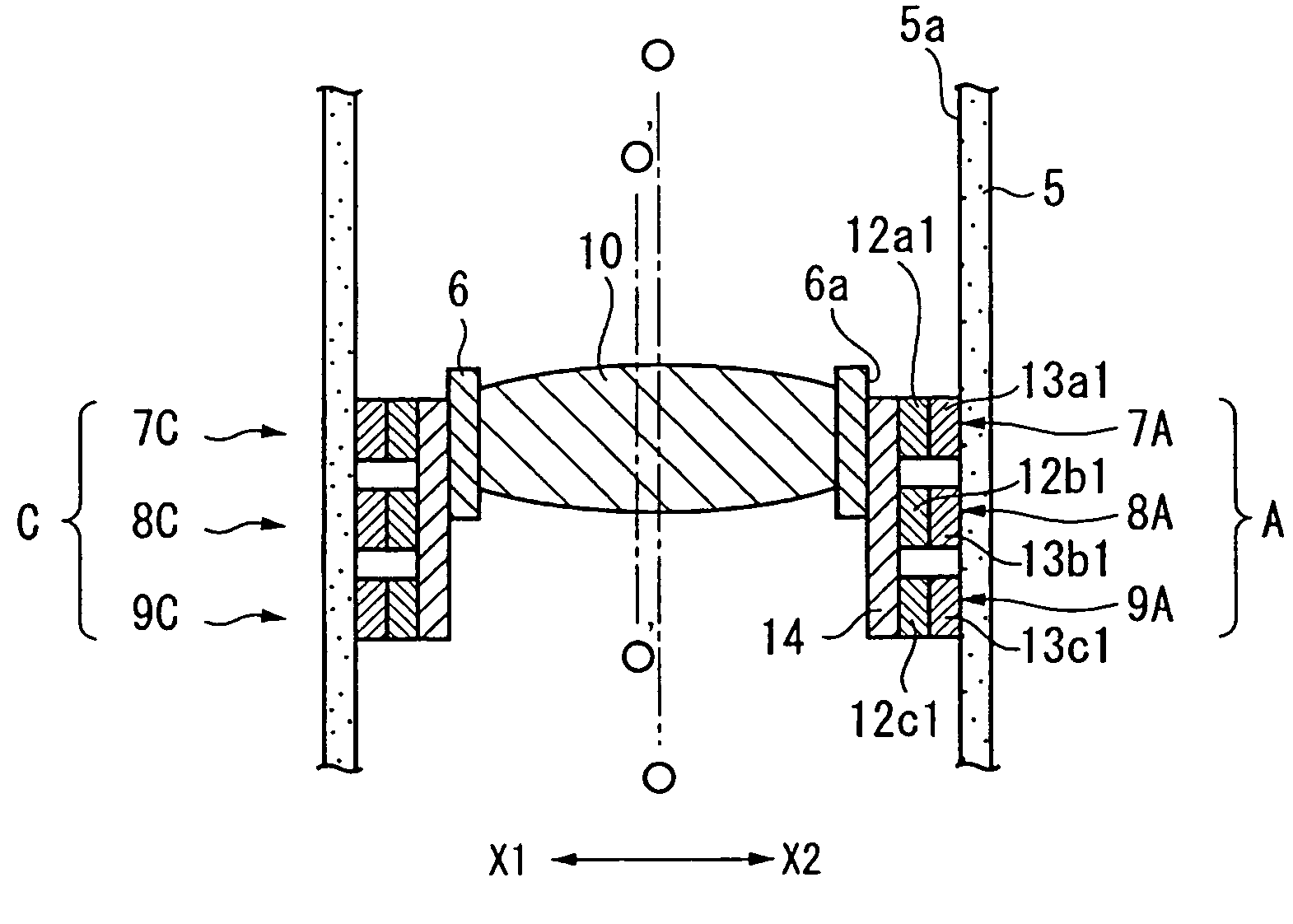
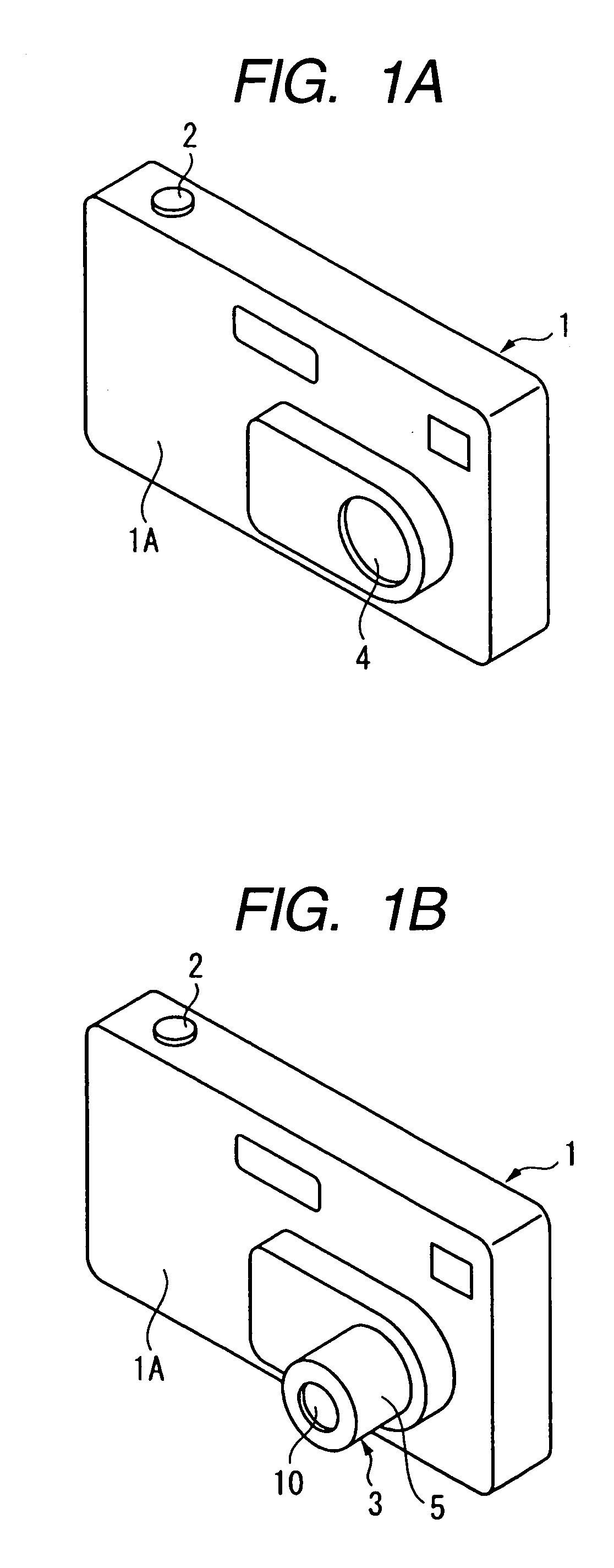
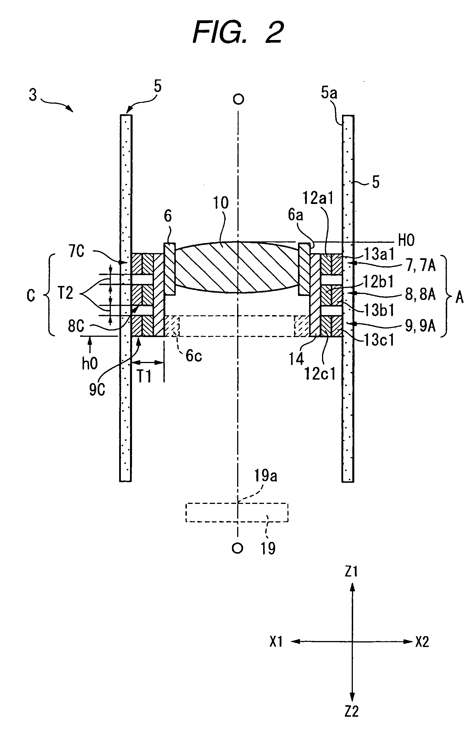
[0039]FIG. 1 is a perspective view showing the appearance of a digital camera having an optical lens adjusting device according to the invention, in which FIG. 1A shows an accommodated state where a lens barrel is accommodated within a camera body, and FIG. 1B shows a protruding state where a lens barrel protrudes out of the camera body; FIG. 2 is a sectional view showing an initial state of a lens barrel part as a component part of the optical lens adjusting device; and FIGS. 3 to 6 are sectional views similar to FIG. 2, for explaining a series of basic operations of the optical lens adjusting device, in which FIG. 3 shows a first operation state, FIG. 4 shows a second operation state, FIG. 5 shows a third operation state, FIG. 6 shows a fourth operation state. Also, FIG. 7 is a partial plan view of an actuator shown in FIG. 2, as viewed from above, and FIG. 8 is a sectional view similar to FIG. 2, showing a state where a plurality of lenses are provided in the lens barrel.

[0040] ...


PUM


Abstract

When a voltage is applied between outside electrodes and a common electrode that constitute driving parts of a driving unit provided between a holder holding a lens and a lens barrel, as shown in FIG. 9, respective dielectric elastomers provided in the driving parts are slightly deformed in a direction that is crushed in an X1-X2 direction. Thus, the entire lens can be slightly moved in the direction of an arrow (X2-direction). This enables an optical axis O′-O′ of the lens to coincide with or get closer to a reference optical axis.

Description

BACKGROUND OF THE INVENTION [0001] 1. Field of the Invention [0002] The present invention relates to an optical lens adjusting device to be mounted on cameras or mobile telephones with a camera, etc. and an adjusting method thereof, and more specifically, to an optical lens adjusting device and an optical lens adjusting method which enables automatic adjustment in cameras. [0003] 2. Description of the Related Art [0004] Prior-art technical literatures related to the invention include, for example, Japanese Unexamined Patent Application Publication No. 2003-66298 (hereinafter referred to as Patent Document 1). The invention disclosed in Patent Document 1 relates to an adjusting device of an optical axis of a photographing lens used for digital cameras, which enables the amount of eccentricity of the lens to be adjusted. [0005] In the invention disclosed in Patent Document 1, a stationary lens L1 and an adjusting lens L2 is provided in a lens barrel, and when an X-Y micro-motion stage...

Claims


Application Information

Patent Timeline
Patent Type & Authority Applications(United States)
IPC IPC(8): G02B7/02
CPCG02B7/08G02B7/023G02B27/648G03B3/10G03B13/32
Inventor YAMASHITA, TATSUMAROYOSHIYUKI, HITOSHIHAYASHI, MASAMICHIMATSUO, EIKI
Owner ALPS ALPINE CO LTD
Learn More