Magnetoresistive device, thin film magnetic head, head gimbal assembly, head arm assembly, magnetic disk drive and method of drive magnetoresistive device

a technology of magnetoresistive devices and thin films, applied in the direction of magnetic recording, instruments, data recording, etc., can solve the problems of insufficient heat resistance, insufficient output as a reproducing head, and insufficient output characteristics of thin films magnetic heads, so as to reduce the thickness of magnetoresistive films, the effect of reducing the thickness of the magnetoresistive film and sufficient output characteristics

Active Publication Date: 2006-02-09
TDK CORPARATION
View PDF8 Cites 23 Cited by
  • Summary
  • Abstract
  • Description
  • Claims
  • Application Information

AI Technical Summary

Benefits of technology

[0017] In the method of driving a magnetoresistive device according to the invention, as shown in the above conditional expressions (1) and (2), depending upon a difference between the product of the saturation magnetization and the thickness of the first ferromagnetic layer and the product of the saturation magnetization and the thickness of the second ferromagnetic layer, the direction where a sense current flows is appropriately selected, so the magnetization direction of the first ferromagnetic layer and the magnetization direction of the second ferromagnetic layer are stabilized without reversing, and an exchange coupling force between the magnetization fixed layer and a antiferromagnetic layer is increased.
[0018] The first magnetoresistive device, the first thin film magnetic head, the first head gimbal assembly, the first head arm assembly and the first magnetic disk drive according to the invention comprises a magnetoresistive film including: a fixing layer including IrMn; a magnetization fixed layer including a first ferromagnetic layer having a magnetization direction fixed in a first direction by the fixing layer, an intermediate layer, and a second ferromagnetic layer having a magnetization direction fixed in a second direction opposite to the first direction by the fixing layer which are laminated in order from the fixing layer; a non-magnetic layer disposed on a side of the magnetization fixed layer opposite to a side where the fixing layer is disposed; and a magnetization free layer disposed on a side of the non-magnetic layer opposite to a side where the magnetization fixed layer is disposed and changing its magnetization direction according to an external magnetic field; a pair of conductive lead layers extending so as to be disposed adjacent to at least parts of both end surfaces of the magnetoresistive film and to face each other; and a current supply means for flowing a sense current in a direction where a current magnetic field toward the second direction is generated in the second ferromagnetic layer in an in-plane direction of the laminate of the magnetoresistive film through the pair of conductive lead layers, wherein a predetermined conditional expression (1) is satisfied, so even under a higher temperature environment, the first magnetization direction and the second magnetization direction can be stabilized, and an exchange coupling force between the magnetization fixed layer and the fixing layer can be increased. Therefore, sufficient output characteristics can be stably maintained even under a high temperature environment while responding to a demand for a higher recording density through reducing the thickness of the magnetoresistive film.
[0019] The second magnetoresistive device, the second thin film magnetic head, the second head gimbal assembly, the second head arm assembly and the second magnetic disk drive according to the invention comprises a magnetoresistive film including: a fixing layer including IrMn; a magnetization fixed layer including a first ferromagnetic layer having a magnetization direction fixed in a first direction by the fixing layer, an intermediate layer, and a second ferromagnetic layer having a magnetization direction fixed in a second direction opposite to the first direction by the fixing layer which are la

Problems solved by technology

However, in the case where an ordered alloy (a material requiring a regular atomic arrangement to develop an antiferromagnetic property) such as NiMn or PtMn which is described above is used for an antiferromagnetic layer, in order to secure a sufficient exchange coupling force, the antiferromagnetic layer made of the ordered alloy is required to have a thickness of approximately 10 nm, so the thin film magnetic head cannot sufficiently respond to a demand for a reduction in the profile.
Moreover, the thickness of the antiferromagnetic layer forms a relatively h

Method used


Image

  • Magnetoresistive device, thin film magnetic head, head gimbal assembly, head arm assembly, magnetic disk drive and method of drive magnetoresistive device
  • Magnetoresistive device, thin film magnetic head, head gimbal assembly, head arm assembly, magnetic disk drive and method of drive magnetoresistive device
  • Magnetoresistive device, thin film magnetic head, head gimbal assembly, head arm assembly, magnetic disk drive and method of drive magnetoresistive device

Examples


first embodiment

[0028] At first, referring to FIGS. 1 through 3, the structure of a thin film magnetic head comprising a magnetoresistive device according to a first embodiment of the invention will be described below.

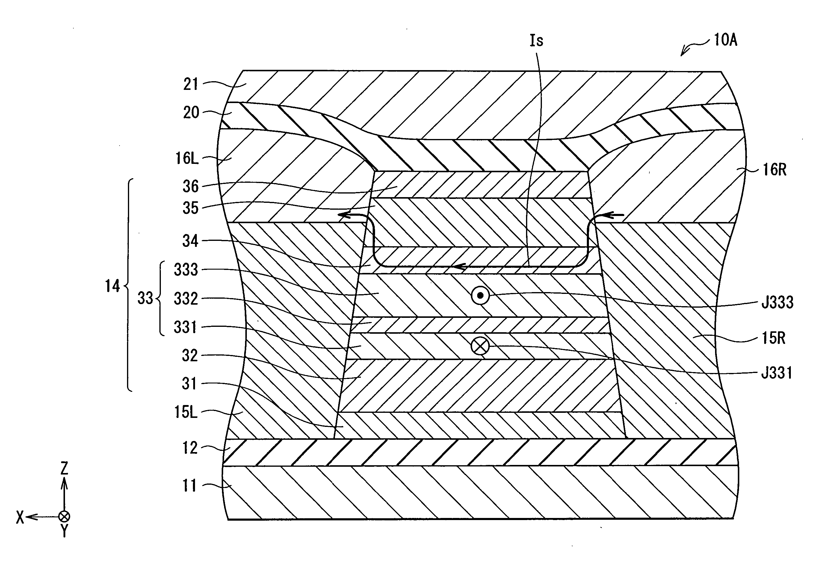
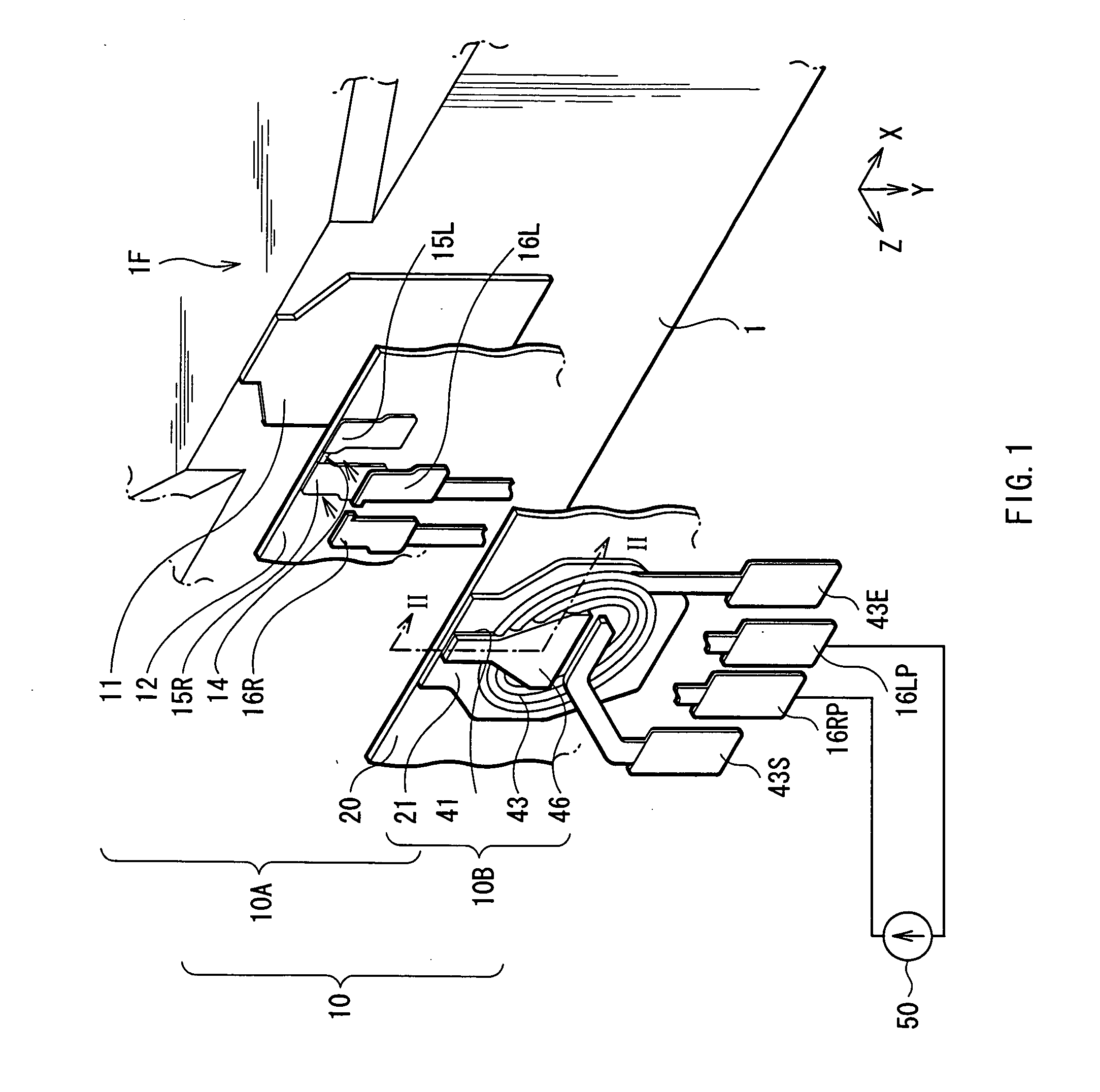
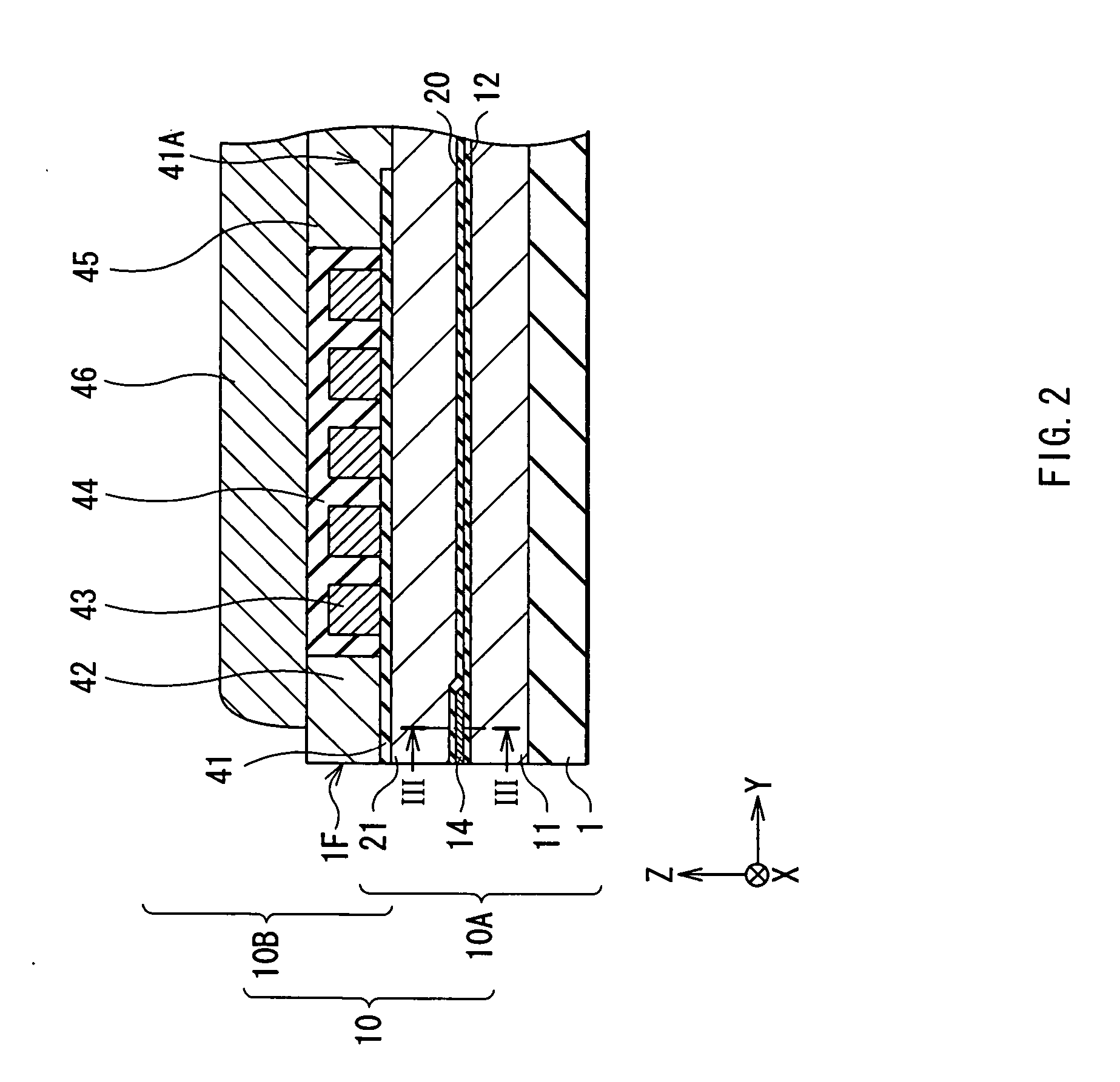
[0029]FIG. 1 is an exploded perspective view of a thin film magnetic head 10 which comprises a reproducing head portion 10A as a magnetoresistive device according to the embodiment, and is formed on a side of a slider in a magnetic disk drive such as a HDD (Hard Disc Drive). FIG. 2 is a sectional view taken along a line II-II of FIG. 1 in the direction of an arrow. FIG. 3 is a sectional view taken along a line III-III of FIG. 2 from the direction of an arrow. FIG. 2 and FIG. 3 show sectional views orthogonal to each other.

[0030] As shown in FIGS. 1 and 2, the thin film magnetic head 10 comprises the reproducing head portion 10A and a recording head portion 10B which are laminated in order as one unit on a side of a block-shaped base substrate 1 which is made of AlTiC (Al2O3.TiC) or ...

second embodiment

[0056] Next, referring to FIG. 4, a thin film magnetic head according to a second embodiment of the invention will be described below.

[0057]FIG. 4 shows a sectional view of the reproducing head portion 10A in the thin film magnetic head 10 according to the embodiment, and corresponds to FIG. 3 in the first embodiment. In FIG. 4, like components are donated by like numerals as of FIG. 3.

[0058] In the following description, only points of the structure of the reproducing head portion 10A and a method of driving the reproducing head portion 10A according to the second embodiment which are different from those in the first embodiment will be mainly described.

[0059] In the first embodiment, the magnetization fixed layer 33 is formed so as to satisfy the conditional expression (1) and a driving method in this case is described above. On the other hand, in the embodiment, the magnetization fixed layer 33 is formed so as to satisfy the following conditional expression (2).

−1.5 mA≦(Ms2×T...

example 1

[0065] In the example, a sense current of 4 mA was applied to the MR film 14 with the following structure under an environmental temperature of 130° C. to examine how the magnetization directions J331 and J333 of the outer pinned layer 331 and the inner pinned layer 333 changed. The results are shown in Table 1.

TABLE 1REVERSAL RATE OFMAGNETIZATION DIRECTION[%]THICKNESSTHICKNESSDIRECTION OF SENSE CURRENTOF OUTEROF INNER+X DIRECTION−X DIRECTIONPINNEDPINNED(ASSISTING(ASSISTINGCONDITIONLAYERLAYERΔ (Ms × T)INNER PINNEDOUTER PINNEDNO.[nm][nm][mA]LAYER)LAYER)11.502.000.76010021.501.950.6808831.501.900.6005741.501.850.5372851.501.800.45141461.501.750.3822071.501.700.3034081.501.650.2348091.501.600.15570101.501.550.08880111.501.500.001000121.551.50−0.081000131.601.50−0.151000141.651.50−0.231000151.701.500.301000161.751.50−0.381000171.801.50−0.451000181.851.50−0.531000191.901.50−0.601000201.951.50−0.681000212.001.50−0.761000

[0066] The MR film 14 of the example included the base layer 31 mad...


PUM


Abstract

Provided is a magnetoresistive device capable of stably maintaining sufficient output characteristics even under a higher temperature environment while responding to a demand for a higher recording density. The magnetoresistive device comprises an MR film including a fixing layer made of IrMn, an outer pinned layer of which the magnetization direction is fixed in a +Y direction by the fixing layer, and an inner pinned layer of which the magnetization direction is fixed in a −Y direction by the fixing layer, a pair of conductive lead layers and a constant current circuit which flows a sense current in a +X direction so as to generate a current magnetic field toward a −Y direction in the inner pinned layer, and in the magnetoresistive device, a conditional expression (1) is satisfied. Thereby, the magnetization directions of the outer pinned layer and the inner pinned layer can be stabilized, so even under a high temperature environment, the magnetoresistive device can obtain stable output characteristics, and can respond to a demand for a higher recording density.

Description

BACKGROUND OF THE INVENTION [0001] 1. Field of the Invention [0002] The present invention relates to a thin film magnetic head, a head gimbal assembly, a head arm assembly and a magnetic disk drive comprising a magnetoresistive device which includes a fixing layer made of an iridium-manganese alloy (IrMn), and a method of driving such a magnetoresistive device. [0003] 2. Description of the Related Art [0004] Conventionally, magnetic disk drives are used as devices recording and reading magnetic information (hereinafter simply referred to as information). The magnetic disk drive comprises, for example, a magnetic disk in which information is stored and a thin film magnetic head which records information onto the magnetic disk and reproduces information recorded on the magnetic disk in an enclosure. The thin film magnetic head comprises a recording head including an air bearing surface (ABS) which faces the magnetic disk and a reproducing head. The reproducing head includes a giant ma...

Claims


Application Information

Patent Timeline
IPC IPC(8): G11B5/33G11B5/127
CPCG11B5/3903
Inventor SHIMAZAWA, KOJITSUCHIYA, YOSHIHIROINAGE, KENJI
Owner TDK CORPARATION
Why Eureka
Try Eureka