Polarization insensitive microbend fiber gratings and devices using the same

a polarization-independent, microbend fiber technology, applied in the direction of cladded optical fibre, instruments, optical elements, etc., can solve the problems of limiting, coupling spectrum also being polarization dependent, inherent polarization sensitivity,

Active Publication Date: 2006-02-09
FURAKAWA ELECTRIC NORTH AMERICA INC
View PDF15 Cites 9 Cited by
  • Summary
  • Abstract
  • Description
  • Claims
  • Application Information

AI Technical Summary

Benefits of technology

[0008] The need remaining in the prior art is addressed by the present invention, which relates to microbend fiber gratings and, more particularly, to forming polarization insensitive microb

Problems solved by technology

One drawback to the use of MIGs is their inherent polarization sensitivity, even when the grating is induced in a perfectly circular fiber.
Since different polarization orientations of the fundamental mode will result in different excitation levels for the four modes, the resulting coupling spectrum will also be polarization dependent—an unwanted result since it severely restricts the applicability of MIGs in fiber optic systems, where a “polarization insensitive” response is often necessary condition.
Looking at the first solution, it has been found to be limiting in the sense that it involves the precision machining of expensive and complex corrugated blocks wi

Method used


Image

  • Polarization insensitive microbend fiber gratings and devices using the same
  • Polarization insensitive microbend fiber gratings and devices using the same
  • Polarization insensitive microbend fiber gratings and devices using the same

Examples


Embodiment Construction

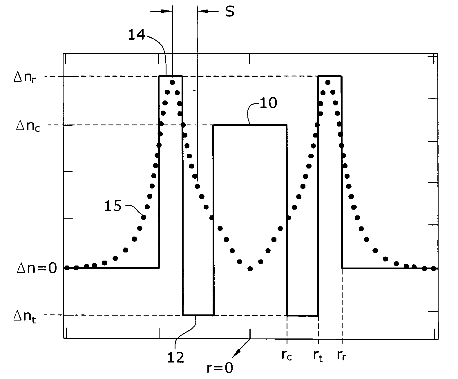
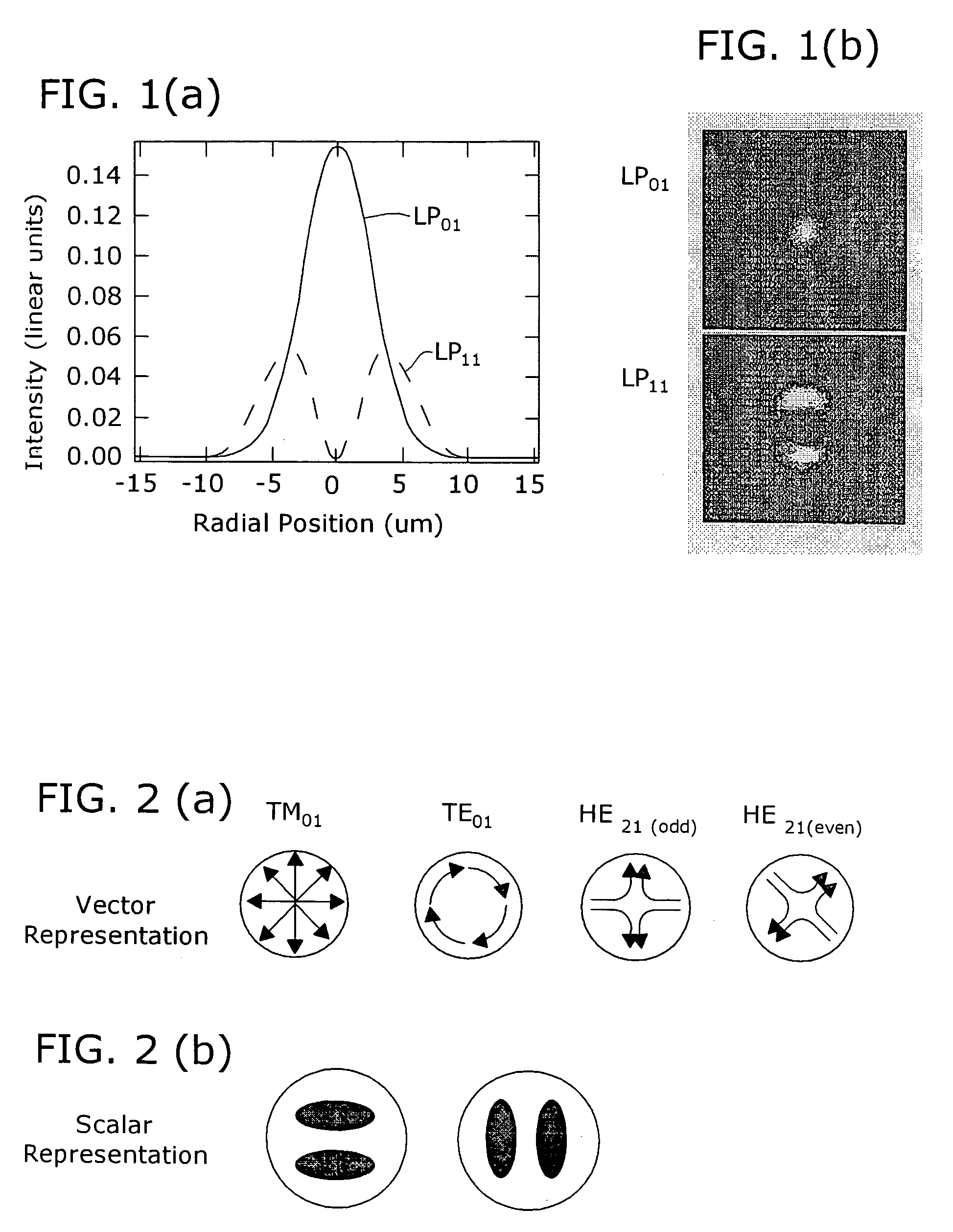
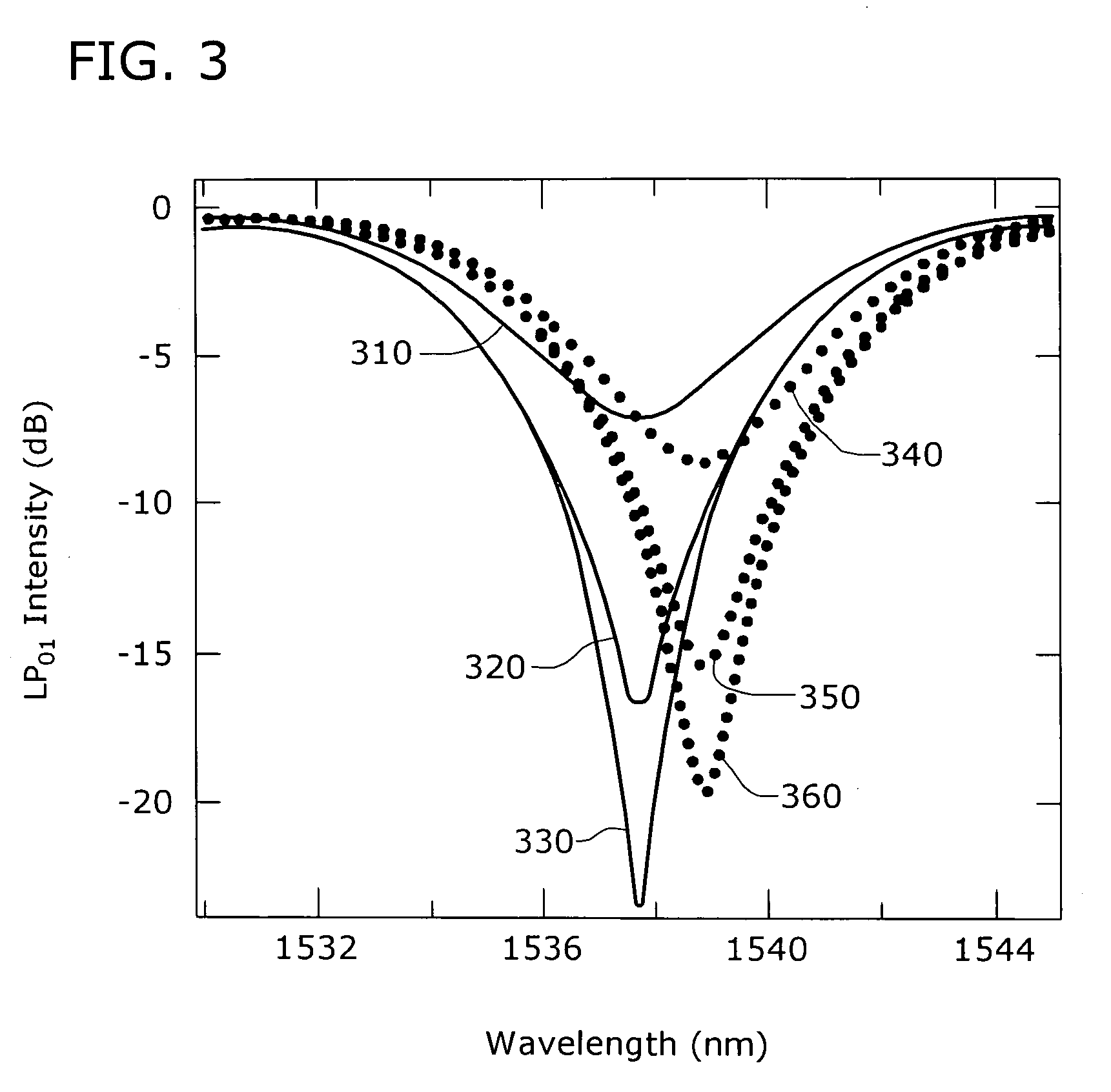
[0027] As will be discussed in detail below, the optical fiber within which a microbend grating is formed is intentionally designed, in accordance with the present invention, such that the propagation constants of the TE0m and TM0m modes are substantially separated from the propagation constant of the odd / even HE2m mode. As a result, the resonant wavelengths associated with the TE0m and TM0m modes will be significantly different / separated from the resonant wavelength of the HE2m mode, where the resonant wavelength of the HE2m mode is then defined as the transmission wavelength for the optical system. For the remainder of the discussion, it will be presumed that radial mode m will be the first order mode, where m=1. It is to be understood, however, that the principles of the present invention are equally applicable to higher order modes.

[0028] It has been found that fibers with substantially large radial gradients in their refractive index profiles (i.e., where a significant portion...


PUM


Abstract

A microbend-induced fiber grating is formed from a section of optical fiber configured to exhibit “splitting” between the resonant wavelengths supported by the TE and TM components of the LP1m mode and the resonant wavelength supported by the odd/even HE2m components of the LP1m mode. Since only the TE and TM components are polarization dependent, by splitting and shifting the resonant wavelengths for these modes away from a system-desired wavelength(s) supported by the odd/even HE modes, a polarization insensitive microbend-induced fiber grating can be formed. A fiber core configuration including a central core region, trench and ring is formed to exhibit a large radial gradient in core refractive index profile, with a significantly steep transition between the ring index and the trench index, to provide the desired splitting between the (undesired, polarization sensitive) TE/TM modes and the HE mode.

Description

TECHNICAL FIELD [0001] The present invention relates to microbend fiber gratings and, more particularly, to forming polarization insensitive microbend fiber gratings by intentionally separating the HE and TE / TM vector modes in a uniquely configured fiber such that only the HE modes are present for the resonant wavelength(s) of interest. BACKGROUND OF THE INVENTION [0002] Tunable broadband mode converters play an important role in wavelength division multiplexed (WDM) optical communication systems. They may be used, for example to dynamically convert a lightwave signal propagating in one mode of a “few mode” fiber into another spatial mode. Such coupling is attractive to alter the path the lightwave signal takes, since the alternate path (defined by the other spatial mode in the fiber) may have preferred dispersion, nonlinearity or amplification properties. An example of this is a higher-order-mode (HOM) dispersion compensator, where light in an entire communication band is switched ...

Claims


Application Information

Patent Timeline
IPC IPC(8): G02B6/02G02B6/036G02B6/028
CPCG02B6/02071G02B6/03644G02B6/02109
Inventor RAMACHANDRAN, SIDDHARTH
Owner FURAKAWA ELECTRIC NORTH AMERICA INC
Why Eureka
Try Eureka