Systems and methods affecting profiles of solutions dispensed across microelectronic topographies during electroless plating processes

Active Publication Date: 2006-02-09
LAM RES CORP
View PDF46 Cites 34 Cited by
  • Summary
  • Abstract
  • Description
  • Claims
  • Application Information

AI Technical Summary

Benefits of technology

[0013] An embodiment of a microelectronic topography resulting from one of the methods and/or one of the apparatuses includes a layer with a bulk composite concentration of one or more elements. The layer includes distinct regions each including a comparatively different thickness and a comparatively different concentration of at least one of the one or more elements.
[0014] An embodiment of another of the methods includes exposing a microelectronic topography arranged within an electroless plating chamber to a deposition solution and introducing a gas into the electroless plating chamber above a plate

Problems solved by technology

In cases in which a film is electrolessly deposited across a microelectronic topography, however, obtaining thickness uniformity may be difficult.
In particular, some electroless plating techniques are susceptible to the “edge effect” in which portions of a film deposited near the edge of the wafer are thinner than the portions of the film deposited near the center of the wafer.
Such an effect also hinders fabrication specifications for depositing films having greater thicknesses near the edge

Method used


Image

  • Systems and methods affecting profiles of solutions dispensed across microelectronic topographies during electroless plating processes
  • Systems and methods affecting profiles of solutions dispensed across microelectronic topographies during electroless plating processes
  • Systems and methods affecting profiles of solutions dispensed across microelectronic topographies during electroless plating processes

Examples


Embodiment Construction

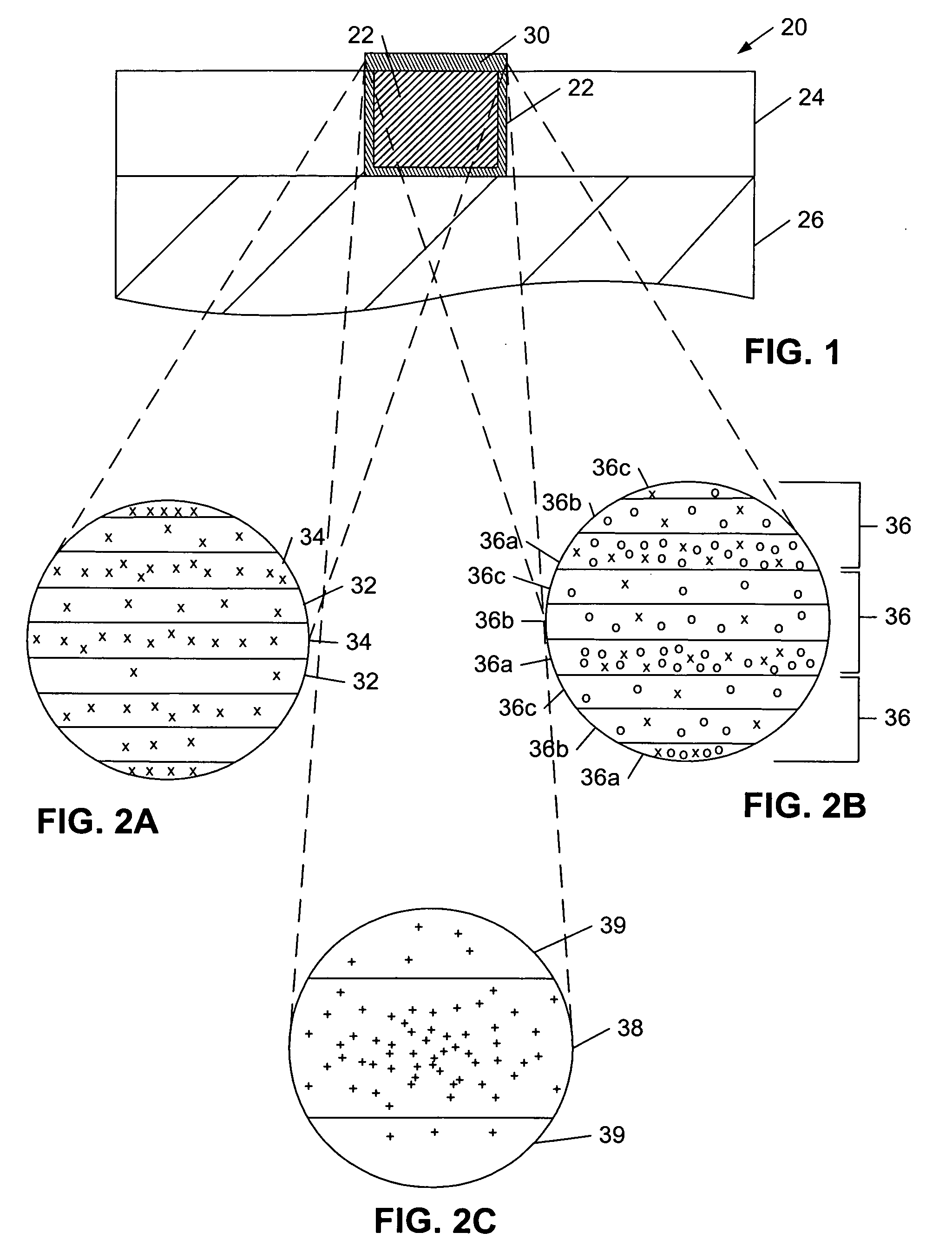
[0039] Turning to the drawings, exemplary methods and systems involving electroless plating processes for the formation of metallic layers and structures within microelectronic topographies are shown. In addition, microelectronic topographies resulting from the use of such methods and systems are shown. For instance, FIG. 1 illustrates a partial cross-sectional view of microelectronic topography 20 having liner layer 28, cap layer 30, as well as other metallic structures which may be formed from the methods and systems described below in reference to FIGS. 3-13. Although the methods and systems described below are specifically discussed in reference to the formation of barrier layers and, therefore, are specific to liner layer 28 and cap layer 30, any of the metallic structures of microelectronic topography 20, including those formed below lower layer 26 and those formed above cap layer 30, may be formed by the methods and systems described below in reference to FIGS. 3-13.

[0040] A...


PUM

PropertyMeasurementUnit
Temperatureaaaaaaaaaa

Abstract

A method is provided which includes dispensing a deposition solution at a plurality of locations extending different distances from a center of a microelectronic topography each at different moments in time during an electroless plating process. An electroless plating apparatus used for the method includes a substrate holder, a moveable dispense arm, and a storage medium comprising program instructions executable by a processor for positioning the moveable dispense arm. Another method and accompanying electroless deposition chamber are configured to introduce a gas into an electroless plating chamber above a plate which is suspended above a microelectronic topography and distribute the gas to regions extending above one or more discrete portions of the microelectronic topography. An exemplary microelectronic topography resulting from the aforementioned methods and apparatuses includes a layer having distinct regions each including a comparatively different thickness and comparatively different concentrations of one of the one or more elements.

Description

PRIORITY APPLICATION [0001] The present application claims priority to provisional application no. 60 / 599,975 entitled “Methods and Systems for Processing a Microelectronic Topography” filed Aug. 9, 2004.BACKGROUND OF THE INVENTION [0002] 1. Field of the Invention [0003] This invention generally relates to methods and systems for processing a microelectronic topography and, more particularly, to methods and systems for depositing films upon microelectronic topographies using electroless plating processes and structures resulting therefrom. [0004] 2. Description of the Related Art [0005] The following descriptions and examples are not admitted to be prior art by virtue of their inclusion within this section. [0006] Electroless plating (also referred to herein as “electroless deposition”) is a process for depositing materials on a catalytic surface from an electrolyte solution without an external source of current. An advantage of an electroless plating process is that it can be selec...

Claims


Application Information

Patent Timeline
IPC IPC(8): C23C26/00B05D1/18
CPCB82Y30/00Y10T428/24612C23C18/1651C23C18/1682C23C18/1683C25D5/08C25D7/12C25D21/10H01L21/288H01L21/6715H01L21/76801H01L21/76826H01L21/76829H01L21/76834H01L21/76843H01L21/76846H01L21/76849H01L21/76858H01L21/76864H01L21/76867H01L21/76877H01L23/53238C25D17/001Y10T428/12Y10T428/12458Y10T428/24479C23C18/1619H01L2924/0002H01L2924/00H01L21/76841
Inventor IVANOV, IGOR C.
Owner LAM RES CORP
Why Eureka
Try Eureka