Fiber optic imaging catheter

a fiber optic imaging and catheter technology, applied in the field of medical devices, can solve the problems of potentially damaging the fiber, repeated torque on the catheter incorporating an optical fiber, etc., and achieve the effects of minimizing the application of undesirable torque, minimizing unduly twisting and damaging the fiber optic cable, and facilitating the use of the catheter

Inactive Publication Date: 2006-02-09
BOSTON SCI SCIMED INC
View PDF98 Cites 102 Cited by
  • Summary
  • Abstract
  • Description
  • Claims
  • Application Information

AI Technical Summary

Benefits of technology

[0005] To overcome the foregoing disadvantage in some applications, the present invention further offers a steerable imaging catheter including a fiber optic cable, which is configured to minimize the application of undesirable torque to the fiber optic cable. To achieve this goal, in one embodiment, a steerable imaging catheter uses at least two cables that bend and steer the catheter. The use of multiple steering cables reduces the need for axially rotating the catheter to achieve a desired bend, and therefore minimizes unduly twisting and damaging the fiber optic cable. In another embodiment of the present invention, a steerable imaging catheter is formed of a catheter tube that has greater flexibility near its distal end portion and has greater stiffness (column strength) in the remainder of the tube. This construction concentrates any flexing and also some torque application at the distal end portion of the tube, while minimizing undue twisting of the tube including the fiber optic cable in the remainder of the tube.
[0006] Specifically, according to one embodiment of the present invention, a steerable imaging catheter is provided, including an elongated catheter tube, at least two steering cables extending along the catheter tube to control the movement of the distal end of the catheter tube, and a fiber optic cable extending through the catheter tube. The catheter may be an imaging-only catheter whose sole function is imaging, or may be any diagnostic / therapeutic catheter having a diagnostic / therapeutic function (e.g., a balloon catheter, stent delivery catheter, sphincterotomy catheter, etc.) in addition to the imaging function. The fiber optic cable transmits illumination light from its proximal end to its distal end and further transmits an image from its distal end to its proximal end. The diameter of the steerable imaging catheter is generally between 1 mm and 4.5 mm, which is smaller than that of a conventional endoscope to permit visualization of a body cavity / lumen that typically cannot be reached by an endoscope. The use of multiple steering cables to control the distal end of the catheter tube permits bending of the distal end in various (two or more) directions in varying degrees. This feature not only prevents undue twisting of the fiber optic cable, but also adds to the maneuverability of the catheter tube, and further significantly increases the range of view of the fiber optic cable.
[0007] According to another embodiment of the present invention, a steerable imaging catheter is provided, including an elongated catheter tube, at least one steering cable extending along the catheter tube to control the movement of the distal end of the catheter tube, and a fiber optic cable extending through the catheter tube. As before, the catheter may be an imaging-only catheter whose sole function is imaging, or may be any diagnostic / therapeutic catheter having a diagnostic / therapeutic function in addition to the imaging function. The catheter tube is constructed so as to have greater flexibility near its distal end portion while having greater stiffness in the remainder of the tube. This may be accomplished, for example, by varying the durometer rating of the materials used to form the catheter tube. Such construction concentrates the flexing at the distal end portion, rather than throughout the entire catheter tube, to thereby reduce undue twisting of the catheter tube along its entire length, and further to permit better control of the movement of the distal end portion.

Problems solved by technology

Consequently, the steerable catheter incorporating an optical fiber is subjected to repeated torque that twists and potentially damages the fiber.

Method used


Image

  • Fiber optic imaging catheter
  • Fiber optic imaging catheter
  • Fiber optic imaging catheter

Examples


Embodiment Construction

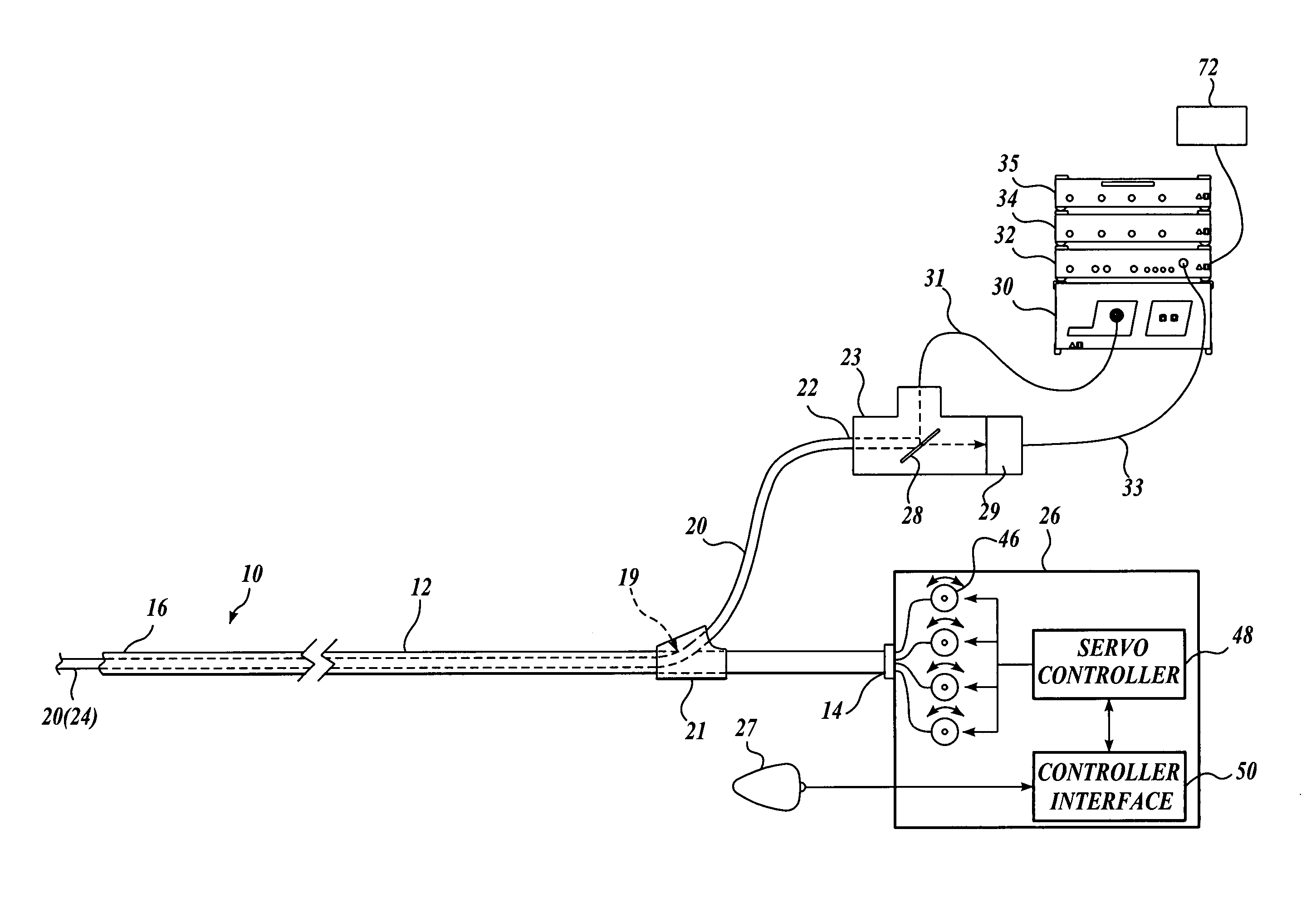
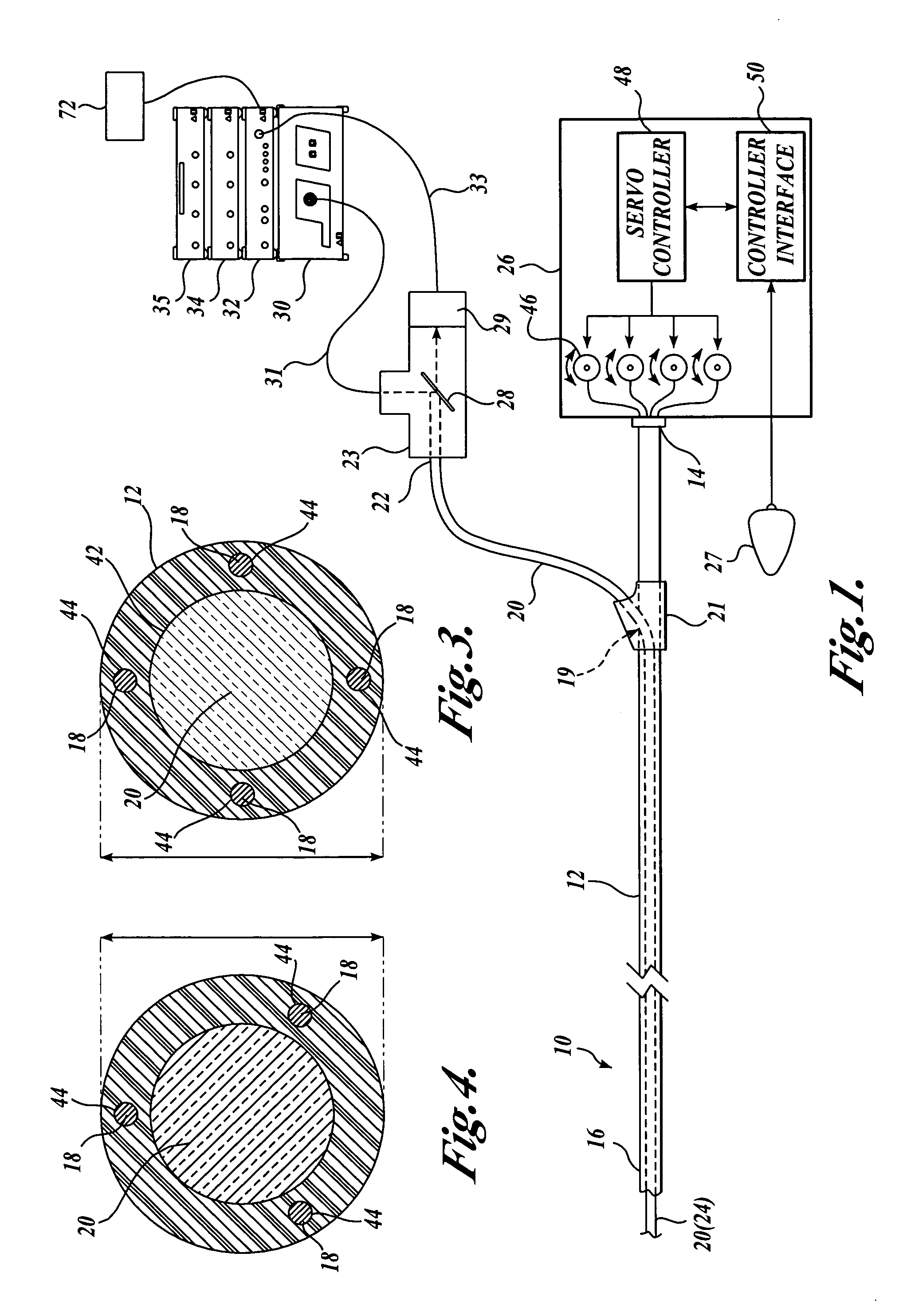
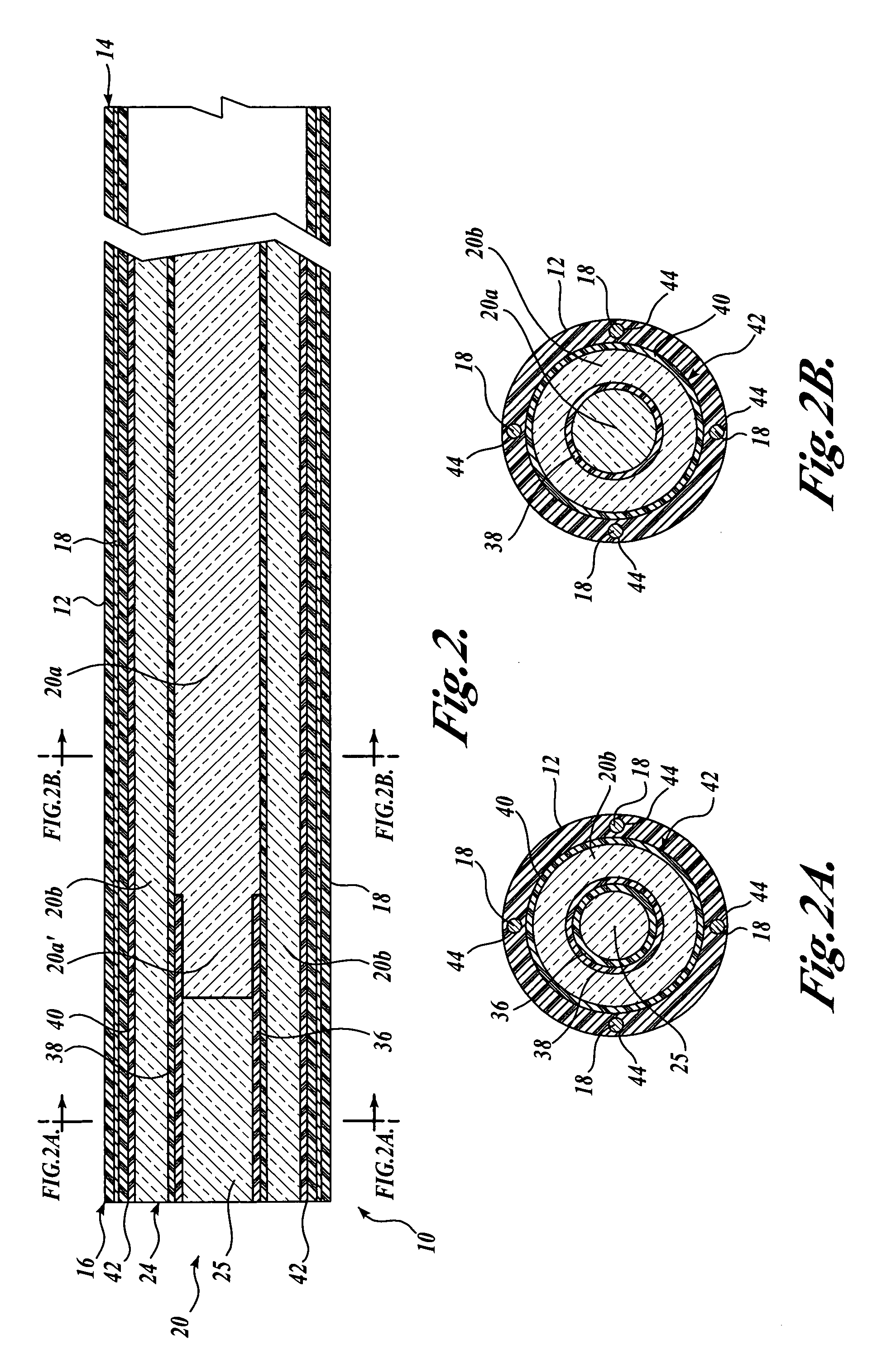
[0023]FIGS. 1-3 illustrate a steerable imaging catheter 10 formed in accordance with the present invention. The catheter 10 includes an elongated catheter tube 12 having a proximal end 14 and a distal end 16. The catheter 10 may be an imaging-only catheter, whose sole function is imaging, or may be any diagnostic / therapeutic catheter having some diagnostic / therapeutic function in addition to the imaging function (e.g., a balloon catheter, stent delivery catheter, sphincterotomy catheter, etc.). Referring specifically to FIGS. 2, 2A, 2B, and 3, four steering cables 18 are positioned at equal distances around the circumference of the catheter tube 12, and extend along the length of the catheter tube 12 substantially from the proximal end 14 to the distal end 16. The steering cables 18 of the catheter tube 12 control the movement of the distal end 16 of the catheter tube. The catheter 10 also includes a fiber optic cable 20 having a proximal end 22 and a distal end 24, which extends at...


PUM


Abstract

A steerable imaging catheter is provided, including an elongated catheter tube, at least one steering cable extending along the catheter tube to control the movement of the distal end thereof, and a fiber optic cable extending along the catheter tube. The fiber optic cable transmits illumination light from its proximal end to its distal end and transmits an image from its distal end to its proximal end. In one embodiment, two or more steering cables are used, and the catheter tube is configured to have greater flexibility near its distal end than its proximal end so as to concentrate the movement (flexing) of the catheter tube at its distal end. The use of two or more steering cables, together with the catheter tube having varying flexibility, permit better control of the distal end of the catheter tube while reducing undue twisting of the remainder of the catheter tube.

Description

FIELD OF THE INVENTION [0001] The present invention relates to medical devices, and in particular to a fiber optic catheter with imaging capabilities. BACKGROUND OF THE INVENTION [0002] An endoscope is a piece of surgical equipment that has imaging capabilities so as to be able to provide images of an internal body cavity of a patient. Most minimally invasive surgical procedures performed in the gastrointestinal (GI) tract or other internal body cavities are accomplished with the aid of an endoscope. An endoscope includes one or more working channels through which other medical catheters / instruments can pass. Typically, an endoscope is used to reach an area of interest within a body cavity and, thereafter, another instrument such as a surgical catheter is extended through the working channel of the endoscope to perform some desired procedure. An endoscope, however, typically has a diameter that is relatively large with respect to the body cavity or body lumen through which it must p...

Claims


Application Information

Patent Timeline
Patent Type & Authority Applications(United States)
IPC IPC(8): A61B1/00A61B1/06A61B1/005A61B1/012A61B1/015A61B1/04A61M25/01
CPCA61B1/00103A61B1/0607A61B1/0052A61B1/00165A61B1/04A61B1/018A61B1/0051A61B1/0057A61B1/07A61B1/015A61B1/00071A61B1/00135A61B2090/3614A61B2090/061A61B2090/306A61B2090/3937A61B1/00117A61B1/00119A61B1/00096A61B1/05
Inventor BOUTILLETTE, MICHAEL P.GRAVES, DAVID MICKYRICHARDSON, M. KEVINFREED, DAVID I.SCOPTON, PAUL M.
Owner BOSTON SCI SCIMED INC
Why Eureka
Try Eureka