Modular orthopaedic implant system with multi-use stems

a multi-use, modular technology, applied in knee joints, medical science, prosthesis, etc., can solve the problems of system requirements still requiring a substantial number of components, failure of primary joint prosthesis, ligamentous instability, etc., to reduce the number of components needed and great flexibility

Active Publication Date: 2006-02-09
DEPUY SYNTHES PROD INC
View PDF29 Cites 185 Cited by
  • Summary
  • Abstract
  • Description
  • Claims
  • Application Information

AI Technical Summary

Benefits of technology

[0020] Although these prior knee implant systems have provided surgeons with great flexibility in meeting patient needs, and the modularity of these syst

Problems solved by technology

On occasion, the primary joint prosthesis fails.
Failure can result from many causes, including wear, aseptic loosening, osteolysis, ligamentous instability, arthrofibrosis and patellofemoral complications.
Although these prior knee implant systems have

Method used


Image

  • Modular orthopaedic implant system with multi-use stems
  • Modular orthopaedic implant system with multi-use stems
  • Modular orthopaedic implant system with multi-use stems

Examples


Embodiment Construction

[0052] A modular orthopaedic knee implant system incorporating the principles of the present invention is illustrated in FIGS. 5-17 of the accompanying drawings. The illustrated modular orthopaedic knee implant system may include components of an existing knee implant system, along with new components that provide the orthopaedic surgeon with the flexibility to assemble a prosthetic knee implant that suits the needs of an individual patient, while reducing the overall inventory of components necessary to provide this flexibility.

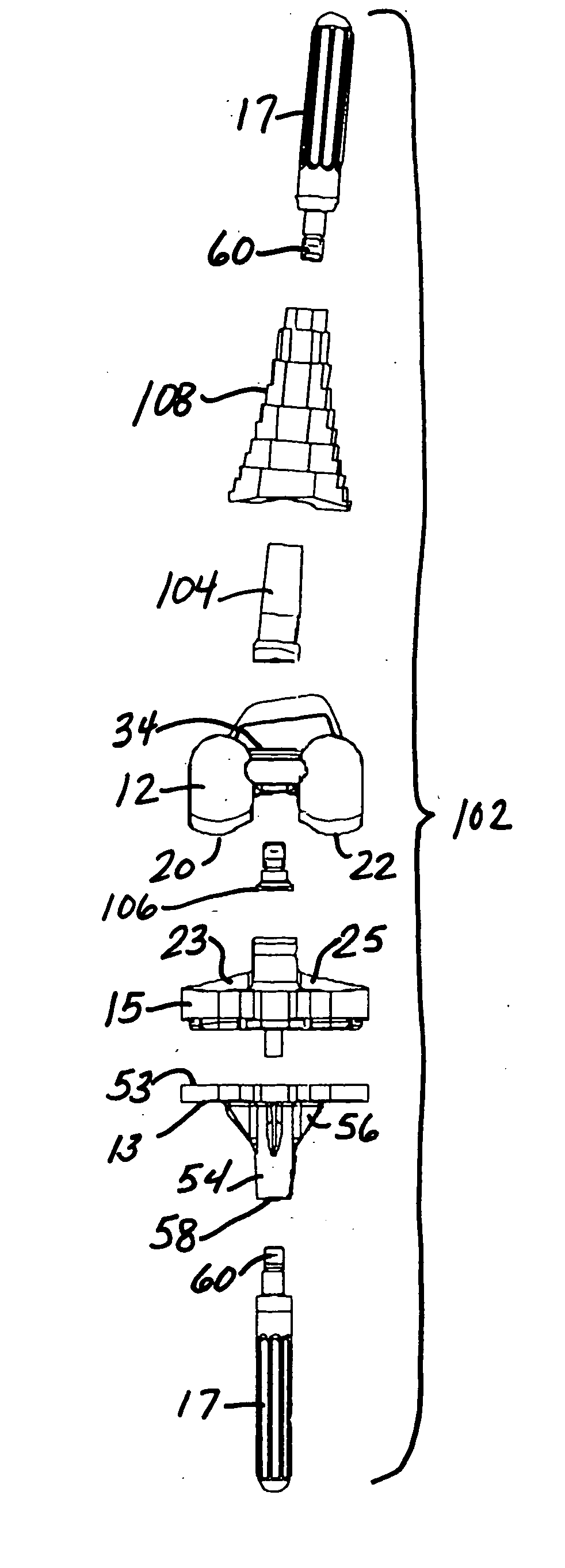
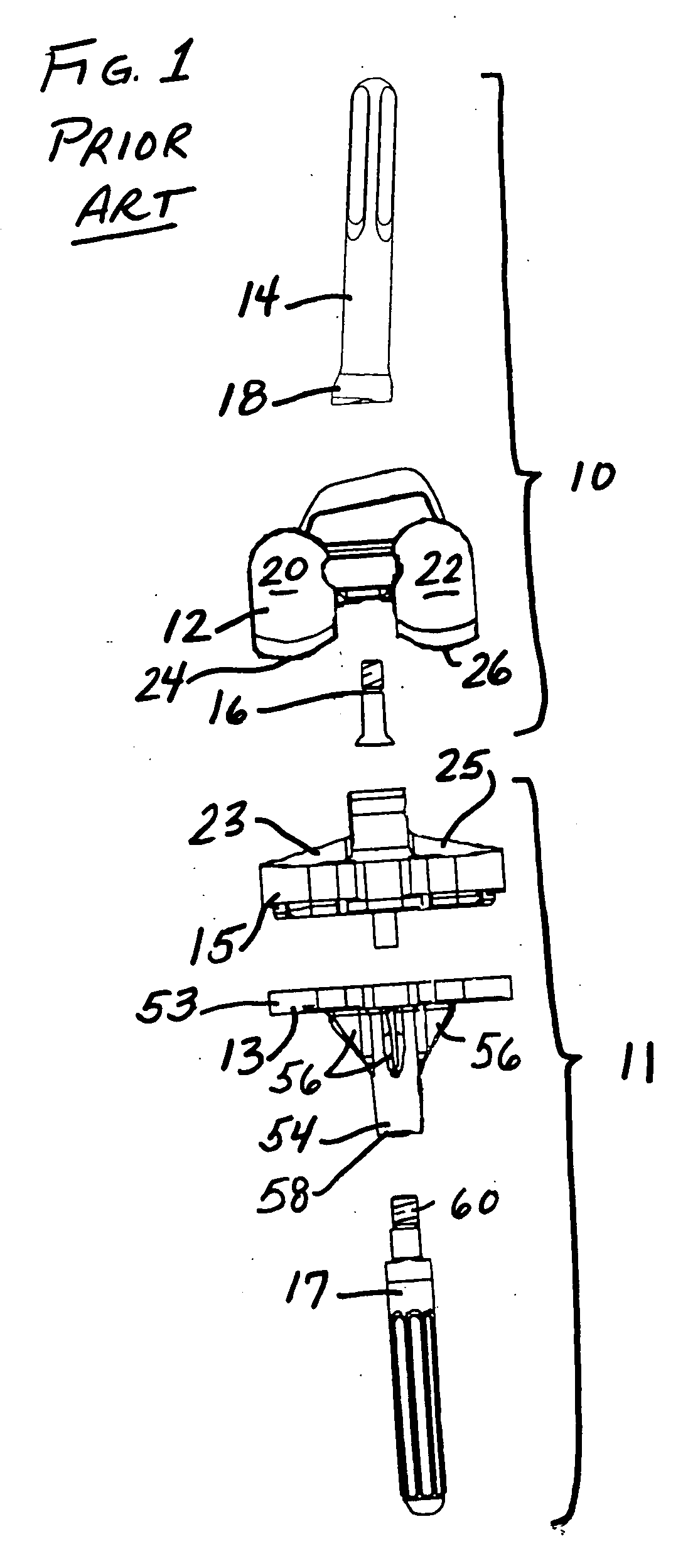
[0053]FIGS. 5-6 illustrate, in exploded views, two exemplary orthopaedic knee implants 100, 102 that may be assembled by a surgeon using the knee implant system of the present invention. These knee implants 100, 102 are shown in FIGS. 7-8, respectively, in an assembled condition. It should be understood that FIGS. 5-8 illustrate implants for use in a patient's right leg; a mirror-image implant would also be used for the patient's left leg.

[0054] Each of th...


PUM


Abstract

A knee implant system includes a femoral adapter. The femoral adapter has a threaded bore so that a stem extension can be threaded onto the proximal end of the adapter. The same stem extension can be threaded onto the distal end of the tibial tray so that the number of stem extensions required in the system is reduced. The femoral adapter has a tapered exterior surface so that a metaphyseal sleeve can be frictionally connected to the femoral adapter. The metaphyseal sleeve has a threaded bore so that the same type of stem extension can be threaded onto the metaphyseal sleeve. The system can include a group of adapters to give the surgeon the option of selecting the appropriate valgus angle and anterior-posterior position of the stem extension.

Description

BACKGROUND OF THE INVENTION [0001] The present invention relates generally to prosthetic joints and, more particularly, to modular orthopaedic knee implant systems. [0002] The knee joint basically consists of the bone interface of the distal end of the femur and the proximal end of the tibia. Appearing to cover or at least partially protect this interface is the patella which is a sesamoid bone within the tendon of the long muscle (quadriceps) on the front of the thigh. This tendon inserts into the tibial tuberosity and the posterior surface of the patella is smooth and glides over the femur. [0003] The femur is configured with two knob-like processes (the medial condyle and the lateral condyle) which are substantially smooth and which articulate with the medial plateau and the lateral plateau of the tibia, respectively. The plateaus of the tibia are substantially smooth and slightly cupped thereby providing a slight receptacle for receipt of the femoral condyles. [0004] When the kn...

Claims


Application Information

Patent Timeline
IPC IPC(8): A61F2/38
CPCA61F2/30721A61F2230/0067A61F2/30767A61F2/38A61F2/3886A61F2002/30215A61F2002/30332A61F2002/30405A61F2002/30434A61F2002/30604A61F2002/30616A61F2002/30736A61F2002/30738A61F2002/30774A61F2002/30878A61F2002/30886A61F2220/0025A61F2220/0033A61F2220/0041A61F2/30734A61F2002/30433
Inventor WRIGHT, ABRAHAM PAUL
Owner DEPUY SYNTHES PROD INC
Why Eureka
Try Eureka