Micro-electromechanical structure with improved insensitivity to thermomechanical stresses induced by the package

a micro-electromechanical and package technology, applied in the field of micro-electromechanical structures, can solve problems such as measurement errors and drifts, alterations in the performance of devices, and the proper operation of micro-electromechanical devices, and achieve the effect of improving the insensitivity to thermomechanical stresses

Active Publication Date: 2006-02-16
STMICROELECTRONICS SRL
View PDF5 Cites 75 Cited by
  • Summary
  • Abstract
  • Description
  • Claims
  • Application Information

AI Technical Summary

Benefits of technology

[0012] Various embodiments of the present invention provide a micro-electromechanical structure that has an improved insensitivity to the thermomechanical stresses induced by the package, so as to overcome the problems highlighted above.

Problems solved by technology

The presence of residual stresses leads to considerable problems for the proper operation of the micro-electromechanical devices.
This leads to alterations in the performance of the devices, in particular measurement errors and drifts, which moreover vary according to the production lot, and at times also between devices belonging to a same production lot.
In fact, in this second case, each anchoring element can undergo, on account of the thermomechanical stresses introduced by the package, a displacement different from the other anchoring elements, causing the deformation of the entire structure, a problem which, instead, does not exist with a single central anchorage.
The solution proposed in the aforementioned U.S. patent does not, however, enable a complete solution of the problems linked thermomechanical stresses, in so far as the rotor anchorage can in any case undergo displacements with respect to at least some of the stator anchorages.
Since the measurement of acceleration is linked to the relative distance between rotor electrodes and stator electrodes, these displacements can lead to measurement errors and drifts.
However, the presence of numerous stator anchorages, and the consequent need to make the corresponding electrical biasing connections, renders it, however, in effect impossible to minimize the distance between all the rotor and stator anchorages, and to position the same stator-anchorages in a position effectively close to the center of the suspended mass.

Method used


Image

  • Micro-electromechanical structure with improved insensitivity to thermomechanical stresses induced by the package
  • Micro-electromechanical structure with improved insensitivity to thermomechanical stresses induced by the package
  • Micro-electromechanical structure with improved insensitivity to thermomechanical stresses induced by the package

Examples


Embodiment Construction

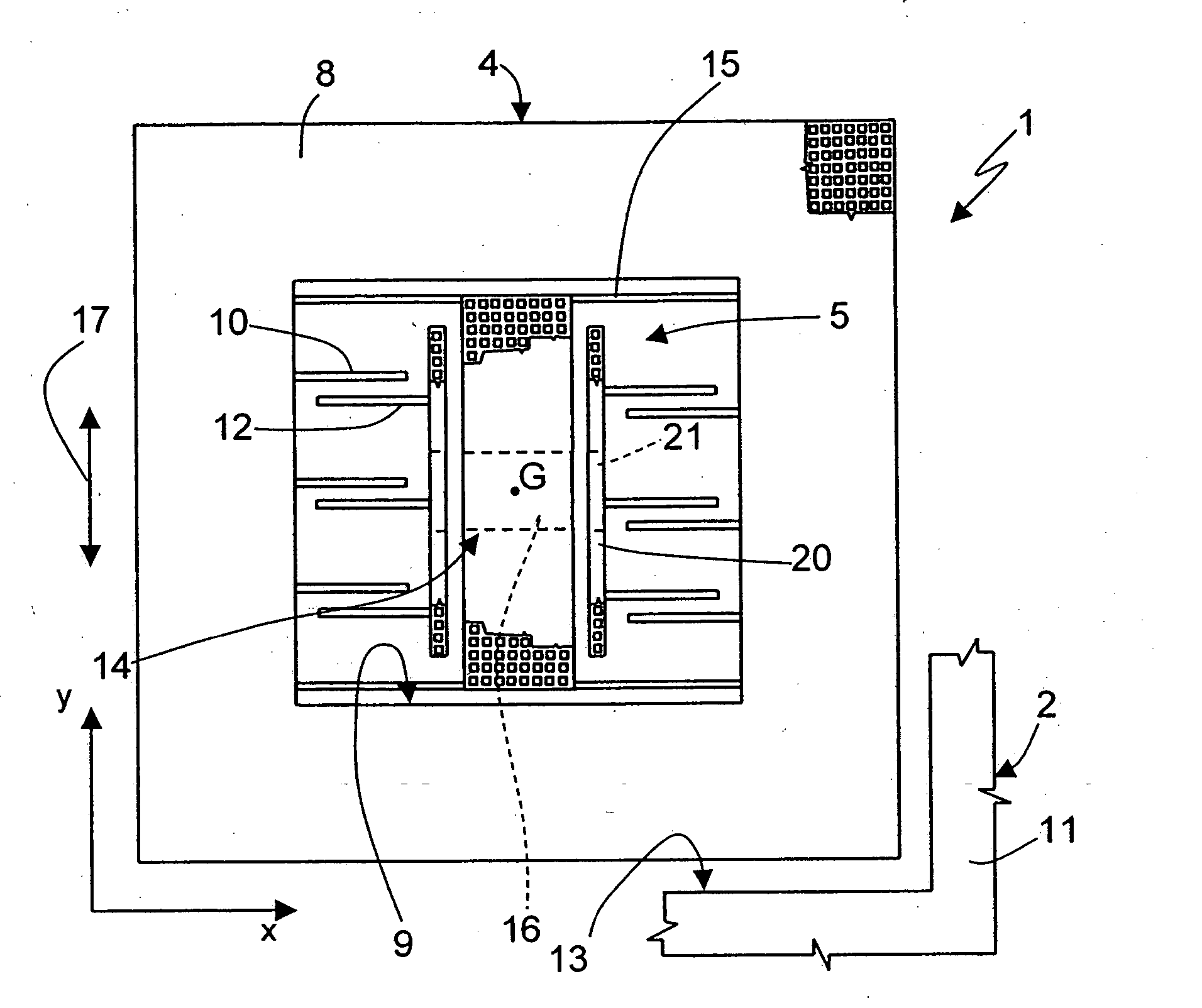
[0023] The general idea underlying the present invention is to anchor both the rotor and the stator of the accelerometer to anchoring regions effectively close to the centroidal axis of the microstructures and very close to one another so as to minimize the relative displacements between mobile parts and fixed parts that can result in drifts in the measures supplied by the sensor.

[0024]FIG. 1 shows an embodiment of a uniaxial accelerometer 1, of a linear type, integrated in a wafer 2 of semiconductor material, and comprising a rotor 4 and a stator 5. In particular, the uniaxial accelerometer 1 has a centroidal axis G (defined as the axis passing through the center of gravity) coinciding with the axis of symmetry of the accelerometer.

[0025] The rotor 4 comprises a suspended mass 8 having substantially the shape of a square frame, surrounded by a fixed structure 11 and separated therefrom by a trench 13. The suspended mass 8 delimits a window 9 having a square shape. In particular, ...


PUM


Abstract

In a micro-electromechanical structure, a rotor has a centroidal axis and includes a suspended structure which carries mobile electrodes. A stator carries fixed electrodes facing the mobile electrodes. The suspended structure is connected to a rotor-anchoring region via elastic elements. The stator includes at least one stator element, which carries a plurality of fixed electrodes and is fixed to a stator-anchoring region. One of the rotor-anchoring regions and stator-anchoring regions extends along the centroidal axis and at least another of the rotor-anchoring regions and stator-anchoring regions extends in the proximity of the centroidal axis.

Description

BACKGROUND OF THE INVENTION [0001] 1. Field of the Invention [0002] The present invention relates to a micro-electromechanical structure, in particular to an accelerometer, with improved insensitivity to the thermomechanical stresses induced by the package. [0003] 2. Description of the Related Art [0004] As is known, micromachining techniques enable manufacturing of micro-electromechanical structures (MEMS) within layers of semiconductor material, which have been deposited (for example, a polycrystalline silicon layer) or grown (for example, an epitaxial layer) on top of sacrificial layers, which are removed via chemical etching. [0005] In particular, accelerometers obtained using micromachining techniques comprise mobile regions (rotor regions) suspended with respect to a substrate, and fixed regions (stator regions) fixed to the substrate and in particular to the package of the accelerometer. The rotor regions are connected to the substrate through elastic biasing elements (called...

Claims


Application Information

Patent Timeline
Patent Type & Authority Applications(United States)
IPC IPC(8): G01P15/08H01L23/48
CPCB81B7/0048G01P15/125G01P1/006B81B2201/0235G01P2015/082
Inventor MERASSI, ANGELOMURARI, BRUNOZERBINI, SARAH
Owner STMICROELECTRONICS SRL
Why Eureka
Try Eureka