Air/oil separating device

a technology of air/oil and separator, which is applied in the direction of liquid degasification, separation process, application, etc., can solve the problems of reducing the quality of the lubricating oil already present in the crankcase, affecting the service life of the crankcase, and affecting the efficiency of the crankcase, etc., to achieve the effect of long and useful life, simple design and economical manufacture and assembly

Inactive Publication Date: 2006-02-16
SHILOH IND INC
View PDF10 Cites 47 Cited by
  • Summary
  • Abstract
  • Description
  • Claims
  • Application Information

AI Technical Summary

Benefits of technology

[0009] Objects, features and advantages of this invention include, but are not limited to, providing an air / oil separating device for removing oil from an air / oil stream such that the removed oil is able to drain from the device and a treated air stream is able to flow out of the device, and providing a design that is of relatively simple design, economical manufacture and assembly, is serviceable, and has a long and useful life in service.

Problems solved by technology

That ignition causes an explosion which burns the air / fuel mixture and initiates the engine's power stroke.
During the power stroke, a certain amount of burnt air / fuel mixture, typically referred to as blow-by gas, blows by the piston ring and leaks between the piston and cylinder wall such that it ends up in the engine crankcase.
If these blow-by gases are not sufficiently removed from the crankcase, they can degrade the quality of the lubricating oil already present within the crankcase, as well as increase the crankcase pressure causing damage to engine components such as seals.
If the air / oil stream is not treated, the entrained oil can negatively impact the combustion process when it mixes with a fresh air / fuel mixture, and the entrained oil can become deposited over the catalytic converter which can reduce its operating life.

Method used


Image

  • Air/oil separating device
  • Air/oil separating device
  • Air/oil separating device

Examples


Embodiment Construction

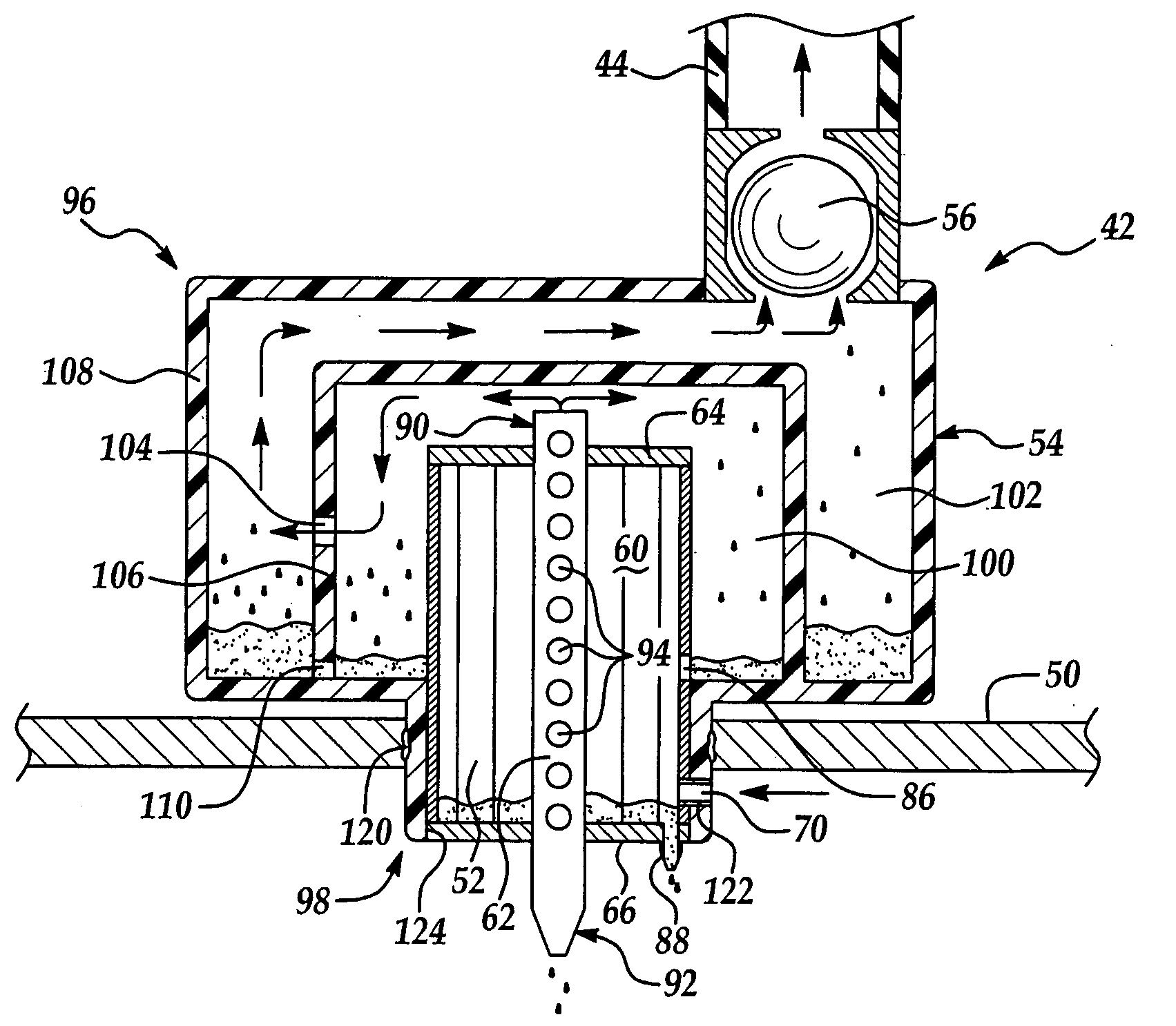
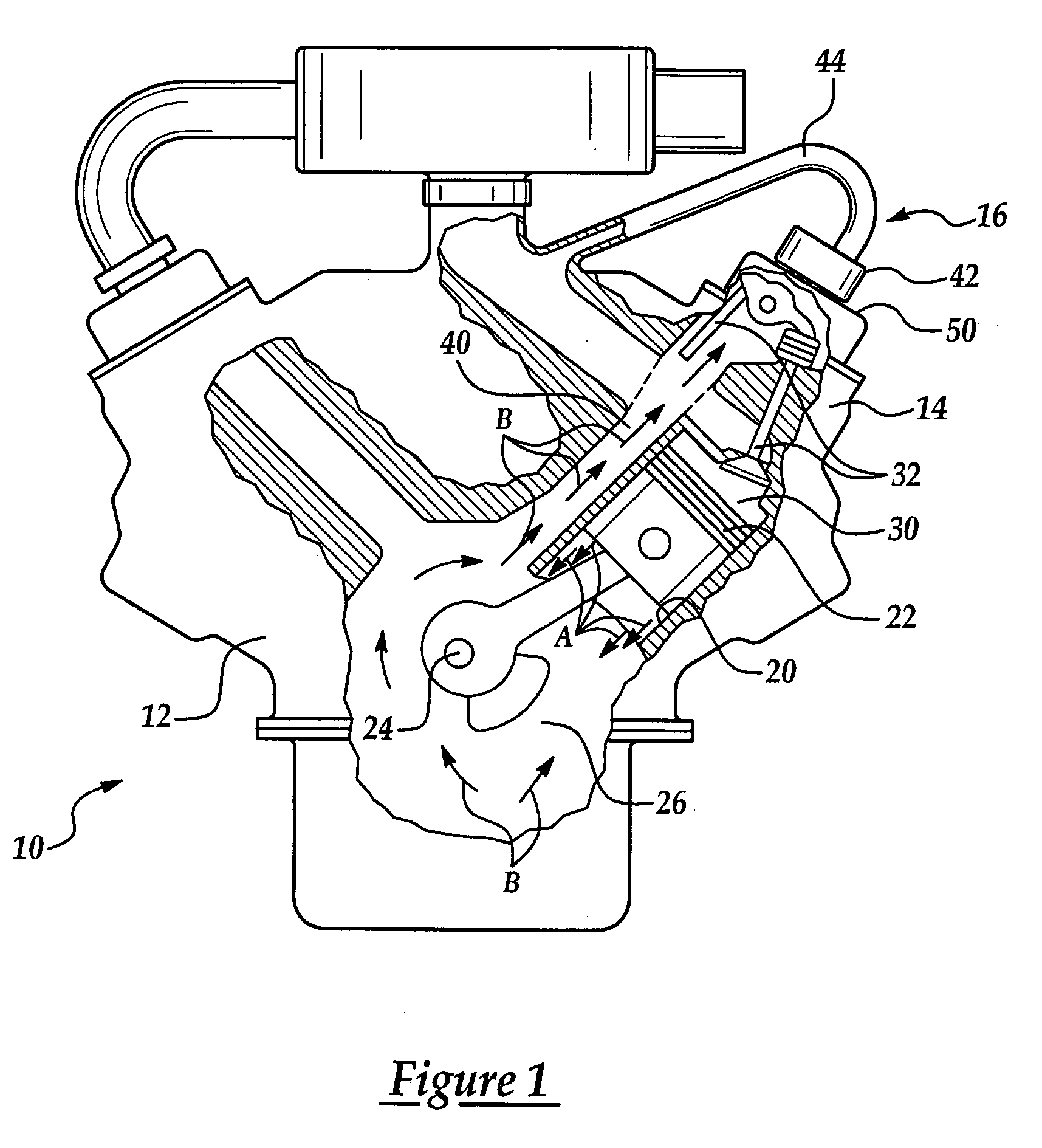
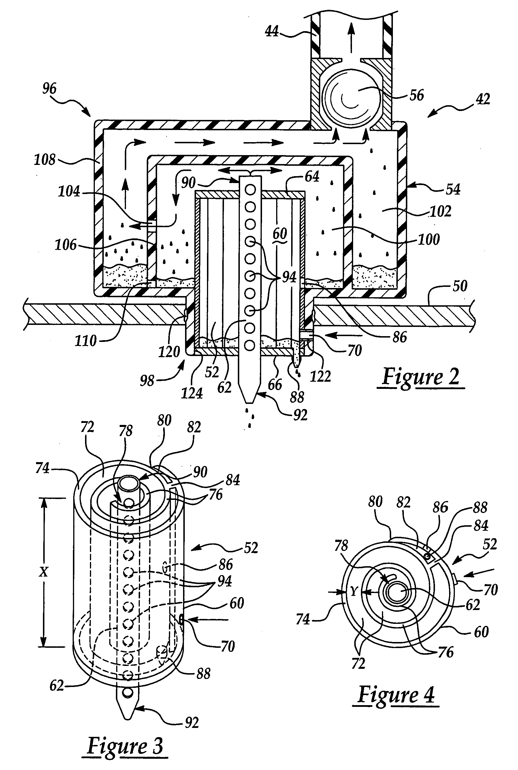
[0015] With reference to FIG. 1, there is shown a V-type multi-cylinder internal combustion engine 10 having an engine block 12, a cylinder head 14, and a crankcase ventilation system (CVS) 16. As is well known in the art, engine block 12 includes a number of cylinders 20 that reciprocally house an equal number of pistons 22. The pistons are each in turn connected to a crankshaft 24 that rotates within a crankcase 26. The cylinder head 14 is mounted atop engine block 12 such that each cylinder 20 has a combustion chamber 30 formed between a lower surface of the cylinder head and an upper surface of the corresponding piston. A set of valves 32 control both the intake and exhausting of gases to and from the combustion chamber, as is widely appreciated in the art. A certain amount of blow-by gas, which is represented by arrows A, enters crankcase 26 where it picks up an oil mist such that the blow-by gases becomes entrained with the oil mist. This air / oil stream, represented by arrows ...


PUM

PropertyMeasurementUnit
flexibleaaaaaaaaaa
axial lengthaaaaaaaaaa
radial widthaaaaaaaaaa

Abstract

An air / oil separating device for removing oil that has become entrained in blow-by gases passing through a crankcase of an internal combustion engine. The air / oil separating device includes a spiral element forming a spiral passageway and a perforated tube. As the air / oil stream passes through the spiral passageway and contacts its walls, a certain amount of the entrained oil is removed or scavenged such that it collects at the bottom of the spiral passageway. The treated air stream, now having less entrained oil, passes into the perforated tube and exits at an upper axial end, while the collected oil drains back into the crankcase via a lower axial end of the perforated tube. The air / oil separating device can be incorporated within a cap assembly also having an oil-fill cap and / or a PCV valve.

Description

TECHNICAL FIELD [0001] The present invention relates generally to a device that separates oil from air, and more particularly, to a device that separates an air / oil stream in an internal combustion engine. BACKGROUND OF THE INVENTION [0002] During operation of an internal combustion engine, an air / fuel mixture is introduced into a combustion chamber and is subsequently ignited by a spark plug. That ignition causes an explosion which burns the air / fuel mixture and initiates the engine's power stroke. During the power stroke, a certain amount of burnt air / fuel mixture, typically referred to as blow-by gas, blows by the piston ring and leaks between the piston and cylinder wall such that it ends up in the engine crankcase. If these blow-by gases are not sufficiently removed from the crankcase, they can degrade the quality of the lubricating oil already present within the crankcase, as well as increase the crankcase pressure causing damage to engine components such as seals. [0003] It i...

Claims


Application Information

Patent Timeline
Patent Type & Authority Applications(United States)
IPC IPC(8): F02M25/06
CPCF01M13/04F01M13/0405F01M13/0416Y10S55/19F02M25/06Y02T10/121F01M2013/0461Y02T10/12
Inventor PRASAD, HARI
Owner SHILOH IND INC
Why Eureka
Try Eureka