
Skateboard with motorized drive and brake systems

a technology of brake system and skateboard, which is applied in the direction of skateboards, vehicle components, propulsion parts, etc., can solve the problems of not being provided with control systems, not in an optimum configuration, and compromising the performance of skateboards

Inactive Publication Date: 2006-02-16
HILLMAN INDS
View PDF20 Cites 45 Cited by
  • Summary
  • Abstract
  • Description
  • Claims
  • Application Information

AI Technical Summary

Benefits of technology

[0013] The brake system associated with the present invention is highly effective as it incorporates a disk well known for its improved brake characteristics. In this case, each of the wheels of the trucks supporting the brake system is provided with a disk that can be mounted against the inner surface of an associated wheel. A single brake pad is operable against an opposing surface of the disk to create the braking action. A mechanical advantage is derived through a lead screw and a pair of levers included in the preferred embodiment.
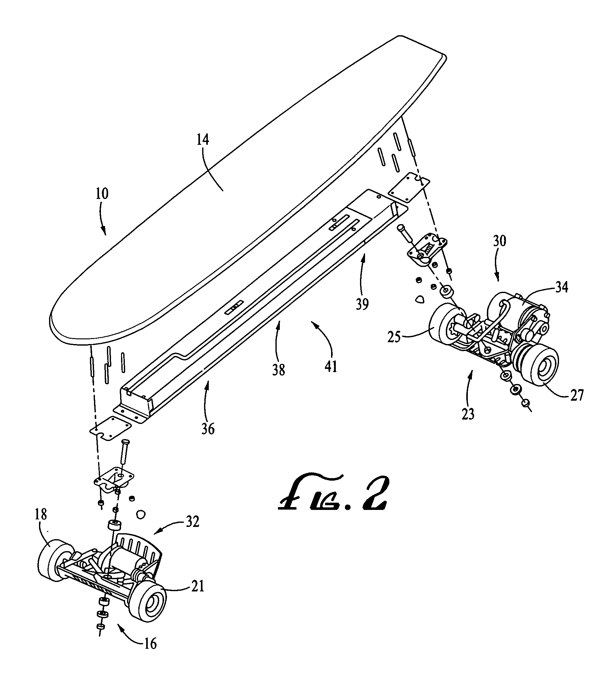
[0017] In another aspect, the invention includes a brake truck adapted for use with a skateboard and including an axle housing and an axle disposed in the housing. A pair of wheels mounted on the axle is rotatable relative to the housing, and a brake disk is rotatable with each one of wheels. A brake pad movable relative to the brake disk functionally engages the disk to inhibit rotation of the disk and the wheel. An actuation assembly is operable to carry the brake pad into frictional engagement with the disk. This assembly includes a lead screw and lever operable to provide a mechanical advantage to the brake pad.

Problems solved by technology

However, when the motor ceases to function, it tends to greatly compromise the performance of the skateboard.
Free-wheel bearings have been contemplated for skateboards, but not in an optimum configuration.
Motorized drive systems have also been contemplated but have not been provided with control systems that take into account the experience of the rider.
These brake systems have been highly mechanical, and their controls unfortunately independent of rider experience.
The braking systems of the past have been relatively ineffective and sometimes totally inoperable, for example if the rider is thrown forward as is typical in a braking maneuver.

Method used


Image

  • Skateboard with motorized drive and brake systems
  • Skateboard with motorized drive and brake systems
  • Skateboard with motorized drive and brake systems

Examples


Embodiment Construction

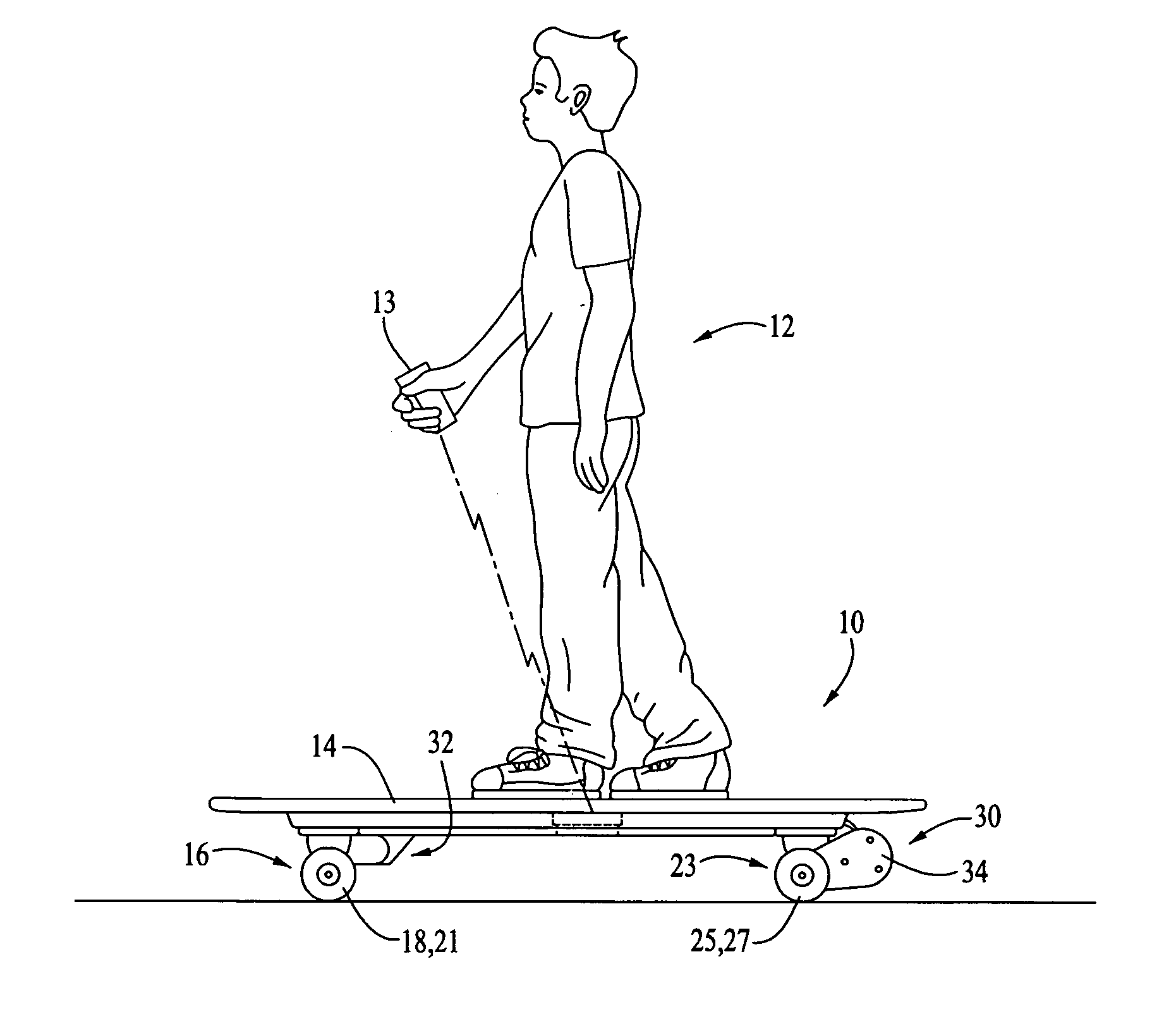
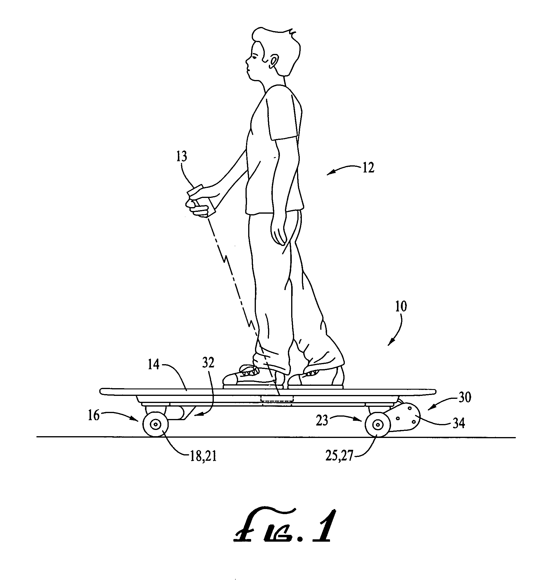
[0034] A skateboard is illustrated in FIG. 1 and designated generally by the reference numeral 10. As illustrated in this view, the skateboard is adapted to be ridden by a rider 12 and operated by a wireless remote control 13.

[0035] In the past, skateboards have been passive in nature, meaning that they have had no motive power of their own, but have relied entirely on the rider 12 for movement. Typically the rider 12 would pump the skateboard with one foot on the skateboard and the other foot on the ground. When a desired level of speed was achieved, the rider 12 would place both feet on the skateboard and coast until additional speed was desired.

[0036] A typical skateboard includes a platform 14 supported by a front truck 16 having a pair of wheels 18 and 21, and a rear truck 23 having a pair of wheels 25 and 27. In the past, all four wheels 18, 21, 25 and 27 have been freewheeling in both a forward direction and a rearward direction.

[0037] In the embodiment illustrated in FIG....


PUM


Abstract

A skateboard includes a motorized drive assembly and a motorized brake assembly, both operable with a wireless remote control to be carried by a rider. The drive assembly is free-wheeling permitting normal use of the skateboard in the event of battery depletion. The brake system includes a motor operable through a simple machine structure to move a brake pad against a brake disk mounted against a wheel. A self-adjustment mechanism presets the brake pad a predetermined distance from the disk prior to brake application. Motor enertia is relied on to store potential energy in a wheel axel in accordance with an associated method of operation.

Description

CROSS REFERENCE TO RELATED APPLICATION [0001] This is a non-provisional application claiming the benefit of co-pending U.S. patent application Ser. No. 10 / 371,488 filed on Feb. 21, 2003, and entitled “SKATEBOARD WITH REMOTE CONTROLLED MOTIVE POWER,” which is fully incorporated herein by reference.REFERENCE TO COMPUTER PROGRAM LISTING APPENDIX [0002] A computer program listing appendix is submitted on a single compact disk, and the material on the disk is hereby fully incorporated by reference. The single compact disk contains the following files: [0003] Name Size Date of Creation NameSizeDate of CreationTransmitter13.5 KBMay 3, 2004Receiver / Motor Controller31.0 KBMay 3, 2004BACKGROUND OF THE INVENTION [0004] 1. Field of the Invention [0005] This invention relates generally to personal transport vehicles and more specifically to skateboards. [0006] 2. Discussion of Related Art [0007] Skateboards were originally intended to transport a rider who provided the only motive power for the...

Claims


Application Information

Patent Timeline
IPC IPC(8): B60K1/00
CPCA63C17/12A63C17/01
Inventor HILLMAN, ROGERCURRAN, KENNETH J.MACKAY, SPENCER L.CRAWFORD, ALAN D.GRAHAM, CLEVE A.CONROY, RICHARD F.
Owner HILLMAN INDS
Learn More