Power unit cooling device

Inactive Publication Date: 2006-02-16
HONDA MOTOR CO LTD
View PDF8 Cites 60 Cited by
  • Summary
  • Abstract
  • Description
  • Claims
  • Application Information

AI Technical Summary

Benefits of technology

[0019] In an embodiment of the invention, a belt type continuously variable transmission which i

Problems solved by technology

That is, since the air introduced from the intake port of the casing is introduced directly into the centrifugal clutch through the flow dividing mechanism in the centrifugal fan, it

Method used


Image

  • Power unit cooling device
  • Power unit cooling device
  • Power unit cooling device

Examples


Embodiment Construction

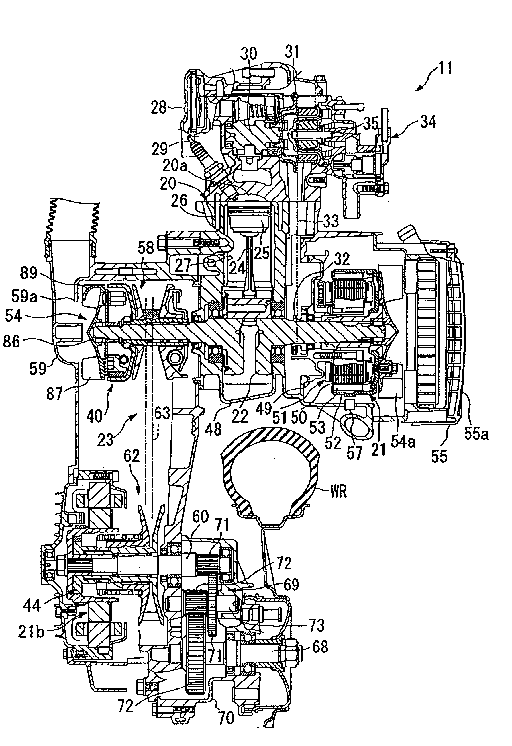
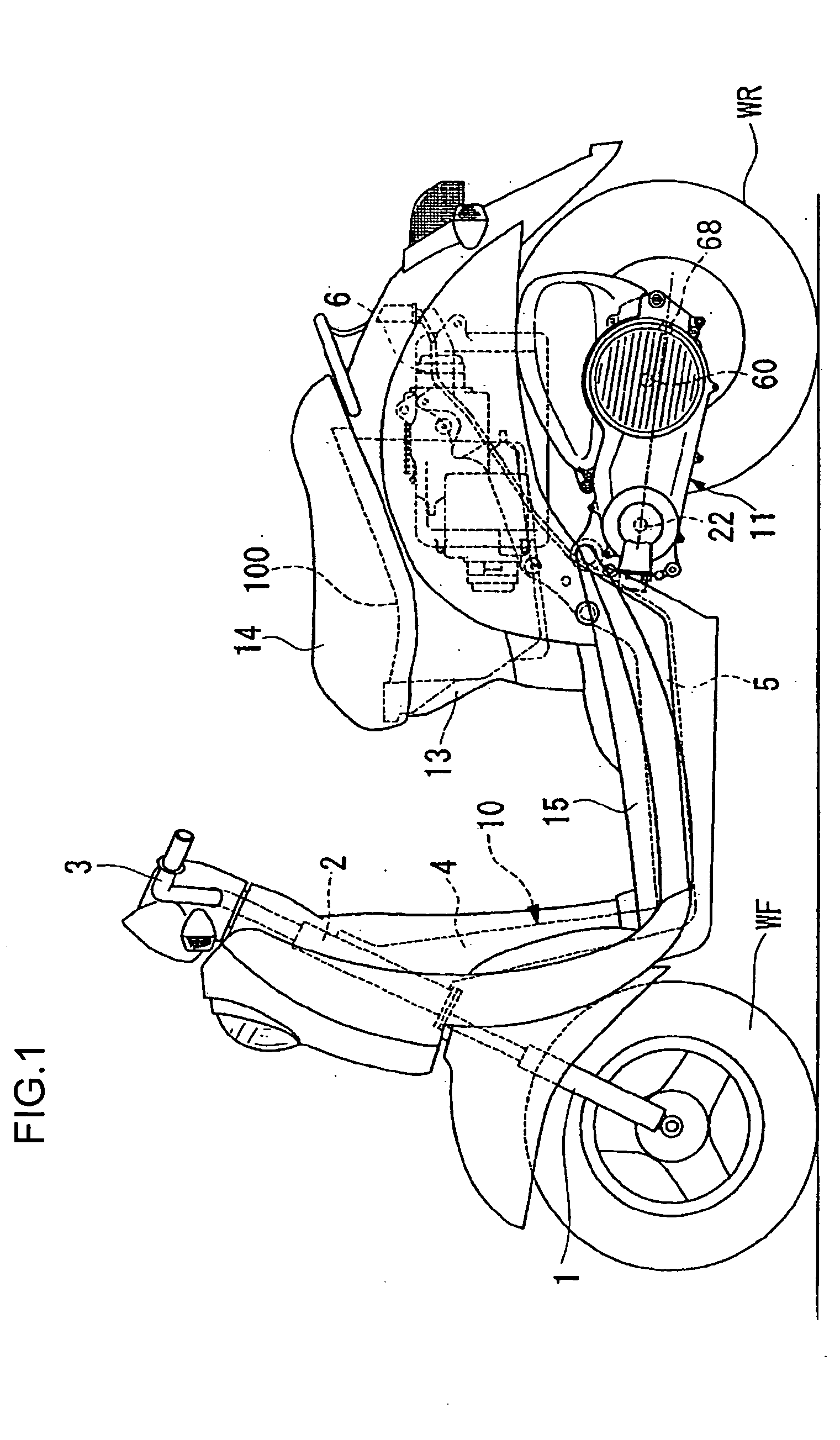
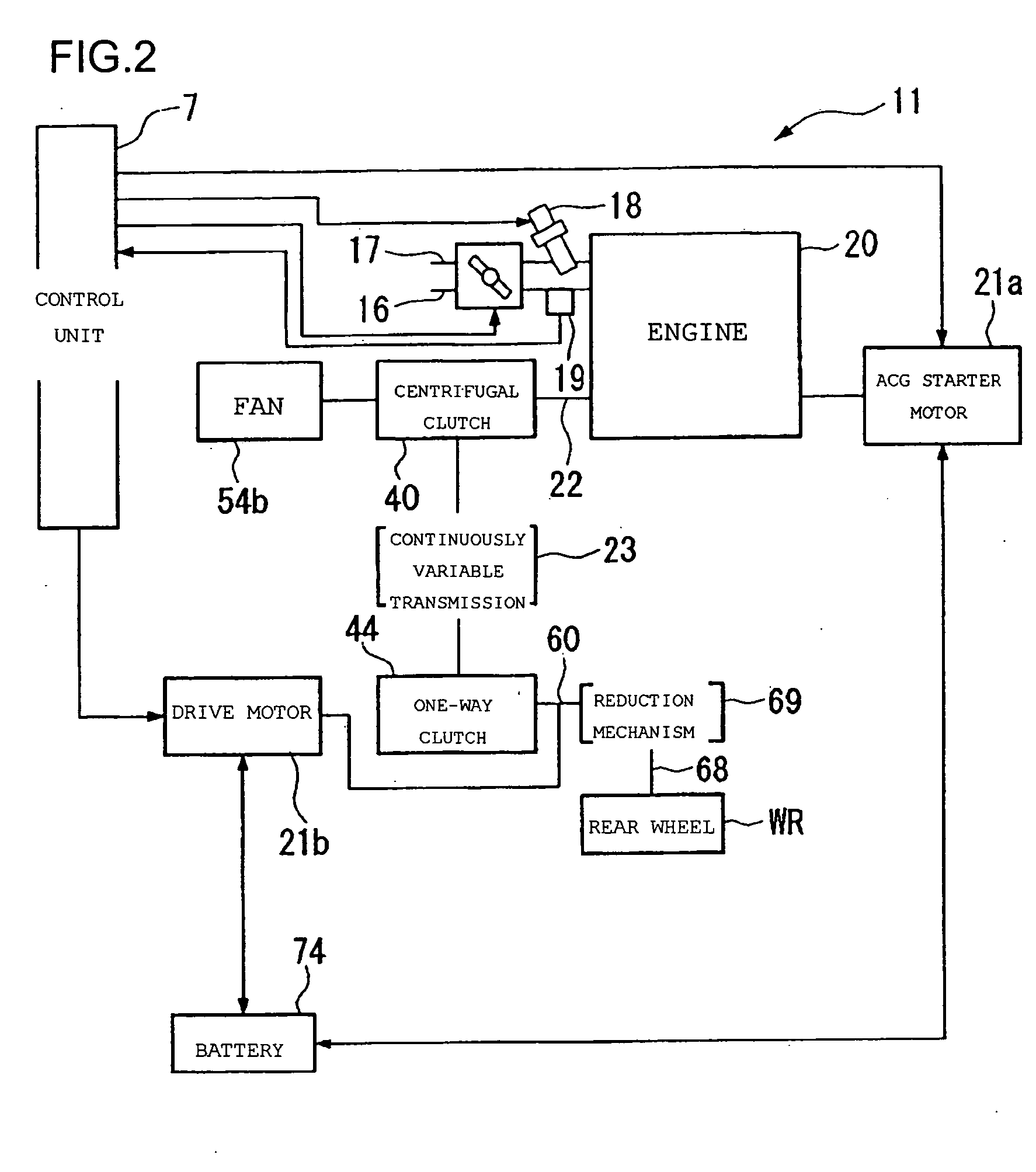
[0028] In the following description, the front side indicates a vehicle advancing direction, and the right side and the left side indicate the right and left, respectively, in the vehicle advancing direction.

[0029] In this embodiment a power unit cooling device according to the present invention is applied to a hybrid motorcycle. As shown in FIG. 1, the motorcycle related to this embodiment is what is called a scooter type vehicle, in which a power unit 11 including a power source is a unit swing type and is supported swingably by a body frame 10 together with a rear wheel WR. On a front side of the vehicle body is provided a front fork 1 which supports a front wheel WF through an axle. The front fork 1 is supported rotatably by a head pipe 2 which constitutes a part of the body frame 10. An upper end of the front fork 1 is connected to a handle 3 and the vehicle can be steered by operation of the handle 3. A down pipe 4 extending in a backwardly downward direction is attached to t...


PUM


Abstract

A centrifugal fan is mounted to an inner plate of a centrifugal clutch as a heat-generating rotating device, and an intake port of a casing is formed near a front side in the axial direction of the centrifugal fan. The centrifugal fan includes a base plate connected to the inner plate of the centrifugal clutch, plural fins formed on the base plate, blow-off holes each formed between arbitrary adjacent fins and extending axially through the base plate, and guide walls for guiding a radially outward air flow over the base plate into the blow-off holes. Air just after admitted from the intake port passes through the blow-off holes and is blown against the centrifugal clutch.

Description

CROSS REFERENCE TO RELATED APPLICATIONS [0001] This application claims priority to JP 2004-233114 filed on Aug. 10, 2004. TECHNICAL FIELD OF THE INVENTION [0002] The present invention relates to a cooling device of an air cooling type which cools the interior of a casing of a power unit with use of an air flow, the power unit being used in a vehicle such as a motorcycle. BACKGROUND OF THE INVENTION [0003] There is known a motorcycle of the type wherein a drive source such as an engine and a power transmission mechanism such as a clutch and continuously variable transmission are accommodated within a single casing and are mounted as a power unit to a vehicle body frame. Since various devices which generate heat with operation of clutch and transmission are accommodated within the casing of the power unit, it is necessary to cool the interior of the casing efficiently. Therefore, many of power units of this type are provided with a cooling device wherein air is introduced from the ext...

Claims


Application Information

Patent Timeline
IPC IPC(8): B62K11/00F16D13/72F01P1/06F16D43/14F16H57/02F16H57/035F16H57/04
CPCB60K6/48B62K2202/00B62M7/12F01P1/06Y02T10/6221F16D43/18F16H57/0415F16H57/0489F16D13/72Y02T10/62F16D2043/145F16D2300/0212B62J50/30F16H57/04
Inventor INOMOTO, YUTAKATSUKADA, YOSHIAKIOZEKI, TAKASHI
Owner HONDA MOTOR CO LTD
Why Eureka
Try Eureka