Eureka AIR delivers breakthrough ideas for toughest innovation challenges, trusted by R&D personnel around the world.

Vehicle sliding floor extension

a technology for sliding floor and rear deck, which is applied in the direction of roof, vehicle with loading gate, transportation items, etc., can solve the problems of reducing the utility of the vehicle, affecting the ability of vehicle owners to effectively haul longer items, and difficulty in accessing the enclosed rear deck

Inactive Publication Date: 2006-02-16
BEQUETTE LAWRENCE M
View PDF16 Cites 12 Cited by
  • Summary
  • Abstract
  • Description
  • Claims
  • Application Information

AI Technical Summary

Benefits of technology

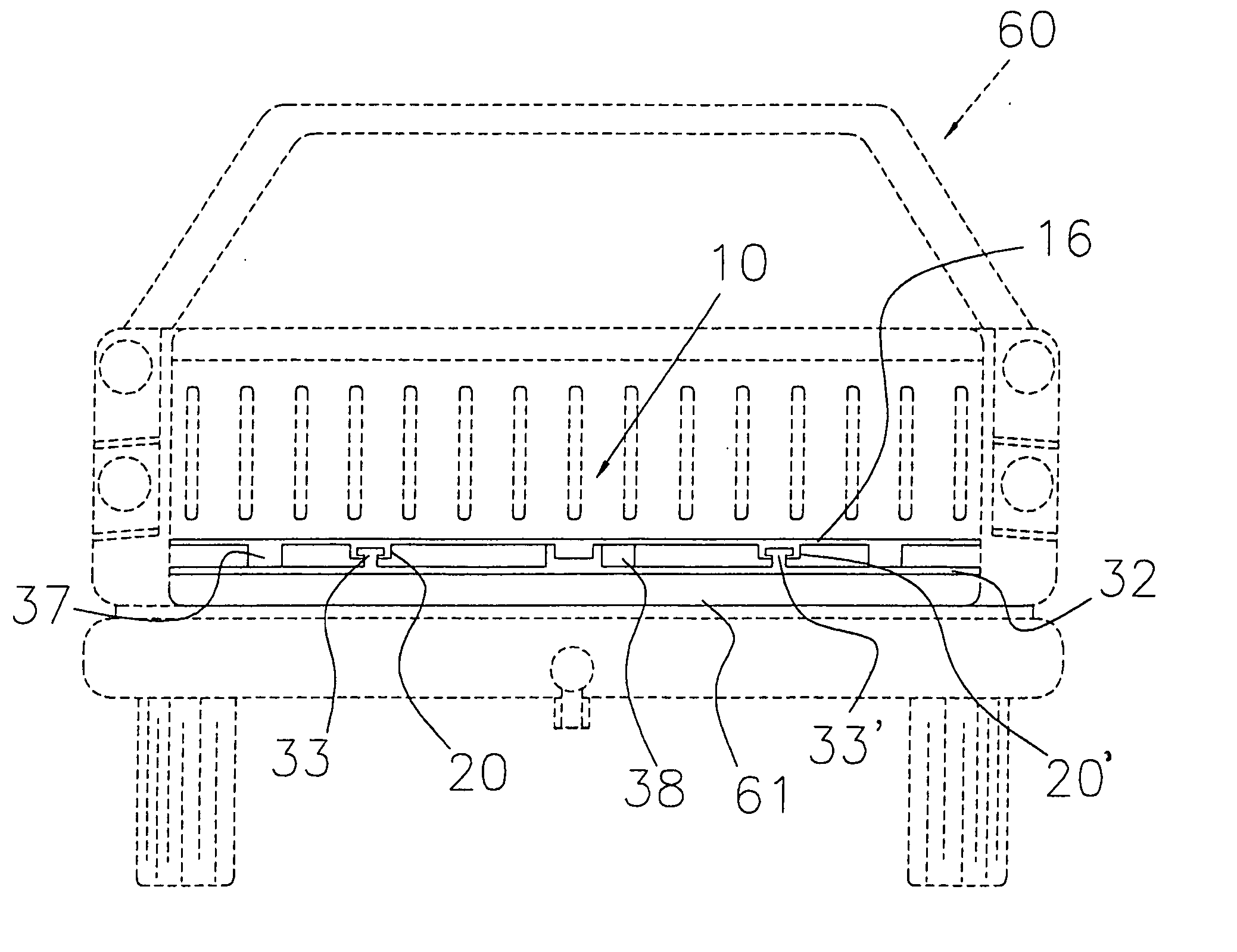
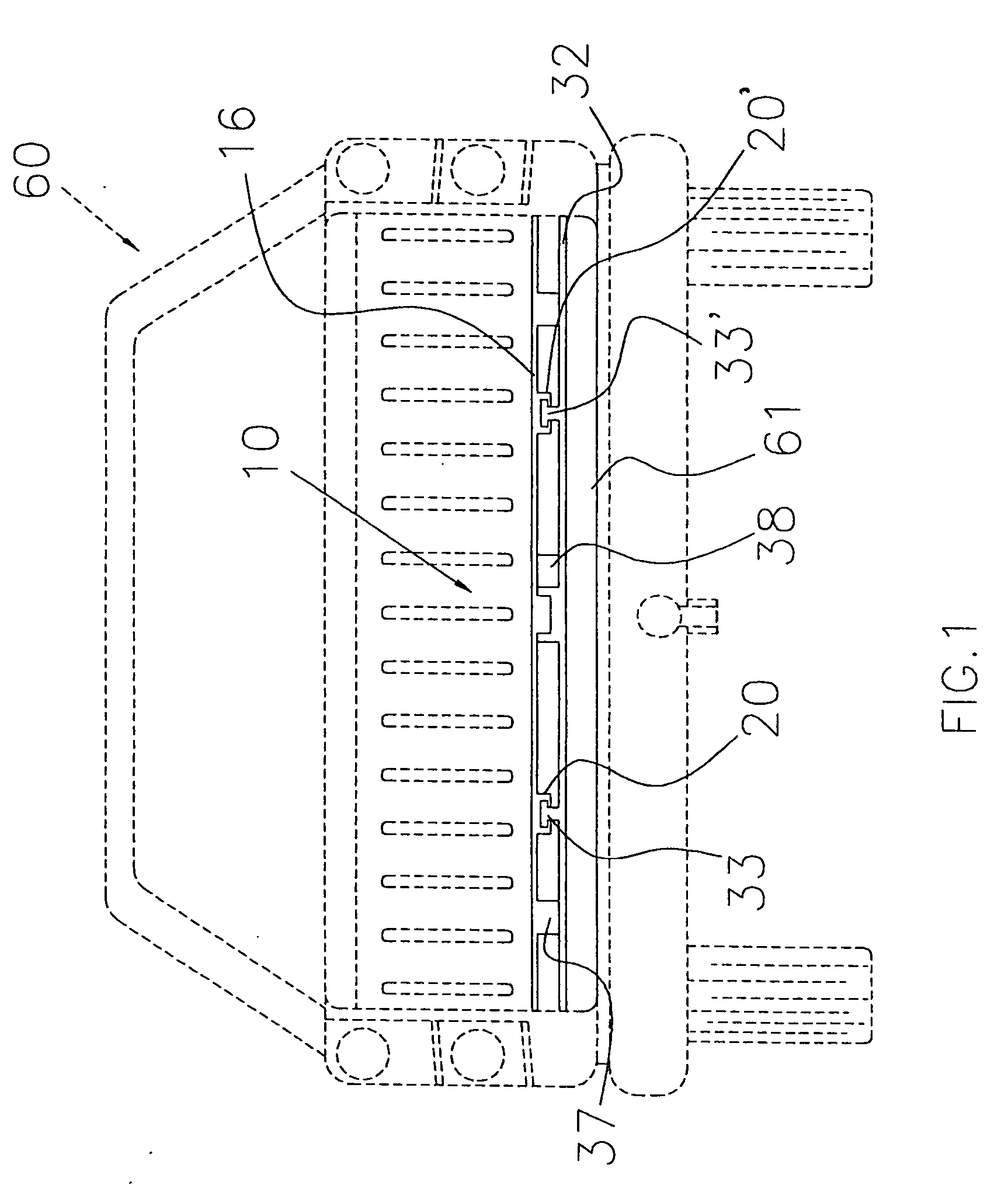
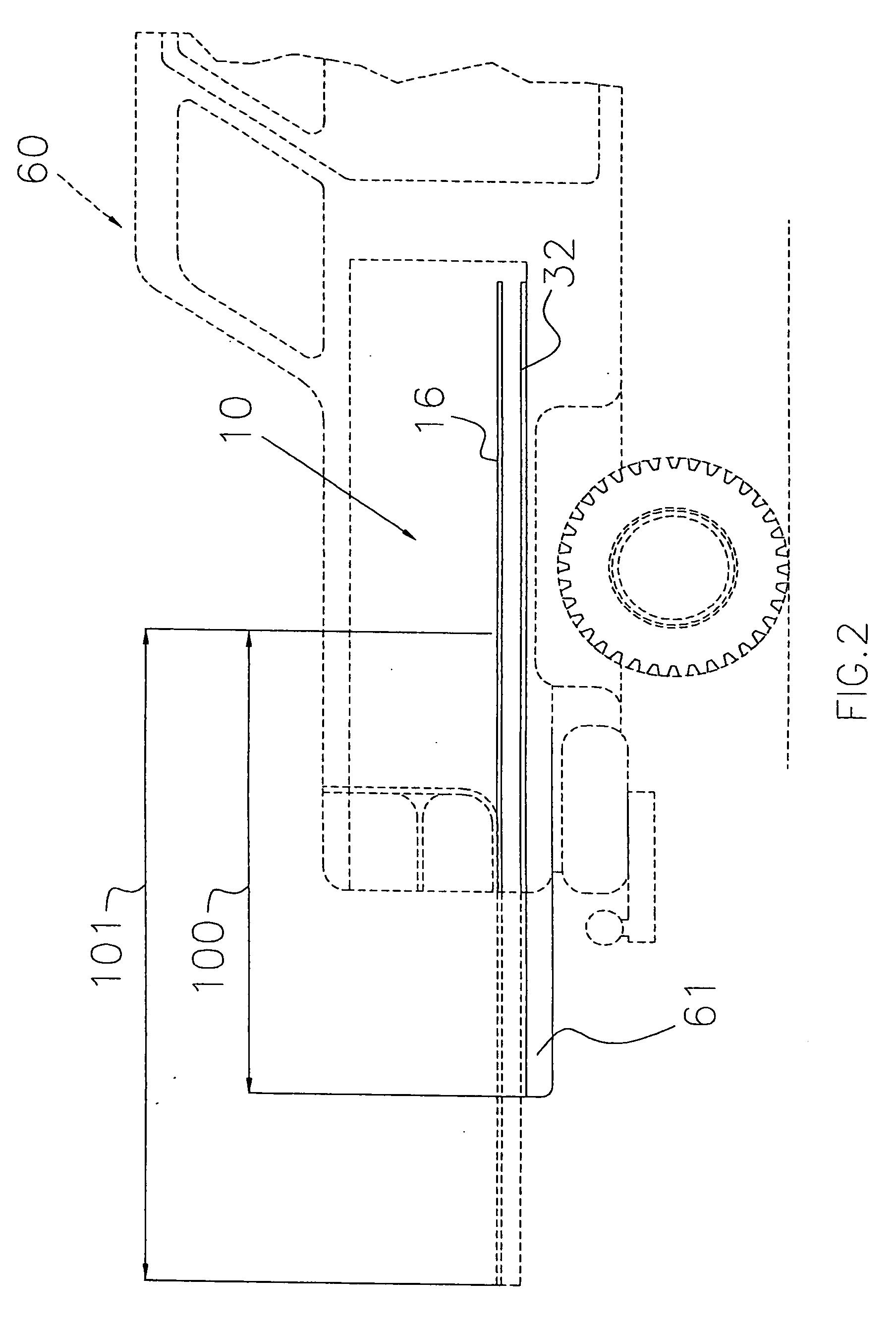
[0012] 1. To provide a vehicle bed floor with an integrated sliding bed extension to increase the utility of shorter beds for hauling longer items;
[0013] 2. To have the bed extension available to facilitate ease of loading and unloading of items stored within the vehicle cargo area.
[0014] 3. To provide a two piece interlocking base / bed extension to be firmly affixed to the existing vehicle bed or deck which is simple in its operation as well as its manufacture.
[0015] 4. To provide a durable deck surface on the bed extension which has a plurality of holes drilled or formed to accommodate the positioning of modular partitions for containing or restraining items being transported.
[0016] 5. To provide motorization whereby the bed extension can be moved even while heavily laden.
[0020] The invention is a base for attachment to the bed of a pickup truck, SUV etc., and an interlocking, slideable deck attached thereto. Both the base and the bed are made of plastic, composite or other durable material. The base is fixed to the vehicle in secure fashion and provides a support for the deck. Motor and braking apparatus are fixed between the base and the deck providing means for moving and controlling the extension of the bed beyond the limits of the existing vehicle bed and tailgate. Holes and other attachment / location means are provided along with multiple modular partitions for securing items against movement while they are being transported. The configuration of the attachment holes in a grid pattern allows for multiple arrangements of the partitions to secure and / or contain a large variety of transported items. The deck surface is textured to decrease friction against loads being carried so that, once the load is unbound or unrestrained, it can easily slide over the deck surface facilitating the management of bulky heavy articles in a manner consistent with the overall intention of the invention.

Problems solved by technology

With the proliferation of compact, mid-size, full-size pickup trucks with short beds and recent developments of hybrid vehicles capable of being converted into pickups to closed rear compartment configurations, limitation is placed on the ability of vehicle owners to effectively haul longer items typically accommodated by longer beds (e.g., a 4 foot×8 foot sheet of plywood.)
Owners of hybrid pickup / SUV vehicles, find difficulty in accessing the enclosed rear deck even with the tailgate down and with one or more top panels removed.
Added to the awkward access to such compartments, the difficulty in sliding something over this high friction surface dramatically decreases the utility of the vehicle.
Simple activities such as grocery shopping are made difficult if not impossible by a person of small stature and even larger, stronger users have trouble reaching and moving items.
U.S. Pat. No. 6,312,034 to Coleman et al. discloses a “drop-in” bed liner / deck extension which addresses a number of the difficulties described and while extension is provided, the attachment methods described, do not allow for safe transport of heavier items for which the vehicle is designed (typically 1000.lbs for a half-ton pickup) nor does it describe any motor means for moving the extension when it may be so loaded and while a braking means is therein described, it does not provide for braking at any point of extension, relying as it does upon a series of holes into which a brake pin is inserted.
A problem faces by owners of such vehicles is how to restrain smaller items or compartmentalize the space to keep items separate.
An additional problem is the discomfort and potential for back injury associated with the necessity of leaning into the cargo area for loading and unloading of heavy cargo items.

Method used


Image

  • Vehicle sliding floor extension
  • Vehicle sliding floor extension
  • Vehicle sliding floor extension

Examples


Embodiment Construction

[0020] The invention is a base for attachment to the bed of a pickup truck, SUV etc., and an interlocking, slideable deck attached thereto. Both the base and the bed are made of plastic, composite or other durable material. The base is fixed to the vehicle in secure fashion and provides a support for the deck. Motor and braking apparatus are fixed between the base and the deck providing means for moving and controlling the extension of the bed beyond the limits of the existing vehicle bed and tailgate. Holes and other attachment / location means are provided along with multiple modular partitions for securing items against movement while they are being transported. The configuration of the attachment holes in a grid pattern allows for multiple arrangements of the partitions to secure and / or contain a large variety of transported items. The deck surface is textured to decrease friction against loads being carried so that, once the load is unbound or unrestrained, it can easily slide ov...


PUM


Abstract

An extendable vehicle cargo floor assembly that includes a semi-rigid material panel base and a slideable panel that slides between guides so as to provide easy access to cargo stored in the vehicle storage part. In another embodiment, the panels are segmented in parts and joined together at installation. In another embodiment, the base panel is not used and instead, a bedliner is configured to operate as the base panel.

Description

RELATED APPLICATIONS [0001] This application is a continuation-in-part of U.S. patent application Ser. No. 10 / 883,248 filed Jul. 2, 2004, which is a continuation-in-part of U.S. patent application Ser. No. 10 / 185,984 filed Jul. 1, 2002, now abandoned, which is a continuation-in-part of U.S. patent application Ser. No. 10 / 068,541 filed Feb. 8, 2002, now U.S. Pat. No. 6,503,036.BACKGROUND OF THE INVENTION [0002] 1. Field of the Invention [0003] This invention relates to truck beds and SUV rear compartments and attachable deck extensions therefore, and more particularly, to a composite / plastic sliding extension plate attached to a truck bed or bedliner or SUV rear compartment by a base plate having molded rails of metal, plastic, or composite to facilitate the controlled movement of the extension plate, the movement of the extension plate being manually or motor actuated. [0004] 2. Prior Art [0005] The present invention relates to motor vehicles specifically relating to an improvement ...

Claims


Application Information

Patent Timeline
IPC IPC(8): B62D33/00
CPCB60P1/003B60P3/40B60R7/02B60P7/0892B60R5/04B60P7/0815
Inventor BEQUETTE, LAWRENCE M.
Owner BEQUETTE LAWRENCE M
Why Eureka
Eureka Blog
Learn More