Ink jet head circuit board, method of manufacturing the same and ink jet head using the same

a technology of circuit boards and ink jets, applied in printing and other directions, can solve the problems of difficult to achieve the function of insulate and protect wires from ink and mechanical and chemical damage, affecting the resistance variation among heaters, and affecting the heat dissipation effect of the heater, etc., to achieve the effect of increasing the resistance of resistors, reducing heater areas, and high precision

Inactive Publication Date: 2006-02-16
CANON KK
View PDF29 Cites 18 Cited by
  • Summary
  • Abstract
  • Description
  • Claims
  • Application Information

AI Technical Summary

Benefits of technology

[0019] The present invention has been accomplished to overcome the above problems and it is a primary object of this invention to make it possible to form heaters with high precision and thereby meet the demand for increased resistance of resistors and reduced heater areas, thus contributing to reduced consumption of electricity, improved heat efficiency, and higher printing resolution and higher image quality.

Problems solved by technology

However, the protective layer is subject to mechanical damages from cavitations caused by creation of bubbles in ink and also to chemical damages caused by chemical reactions between ink components and materials making up the protective layer at high temperatures to which the protective layer's surface in contact with the heater rises immediately after bubbles are formed.
Hence, the function to insulate and protect the wires from ink and the function to protect against mechanical and chemical damages are difficult to achieve at the same time.
So, even minute variations in heater size will greatly affect resistance variations among the heaters.
If resistance variations result in differences in bubble generation phenomenon among the heaters, not only can the required amount of ink for one nozzle not be stably secured but the amount of ink also varies greatly among the different nozzles, leading to a degradation of printed image quality.
However, given a situation where the number of heaters formed in the circuit board is very large and there is a growing trend for reducing the area of individual heaters, it is becoming more and more difficult to secure enough space to allow the electrode wires to be increased in width without increasing the size of the circuit board.
On top of that, increasing the width of electrode wires imposes limitations on high-density integration of small-area heaters or nozzles.
This method, however, renders the improvement in the patterning precision of the heaters difficult.
As described above, it is extremely difficult to meet both of the two requirements at the same time, one for increasing the resistance of resistors and reducing the area of heaters and one for increasing the thickness of electrode wires.

Method used


Image

  • Ink jet head circuit board, method of manufacturing the same and ink jet head using the same
  • Ink jet head circuit board, method of manufacturing the same and ink jet head using the same
  • Ink jet head circuit board, method of manufacturing the same and ink jet head using the same

Examples


first embodiment

[0049] (First Embodiment of Ink Jet Head Circuit Board and Process of Manufacturing the Same)

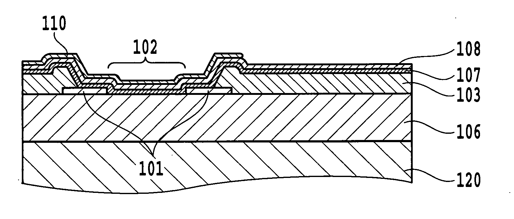
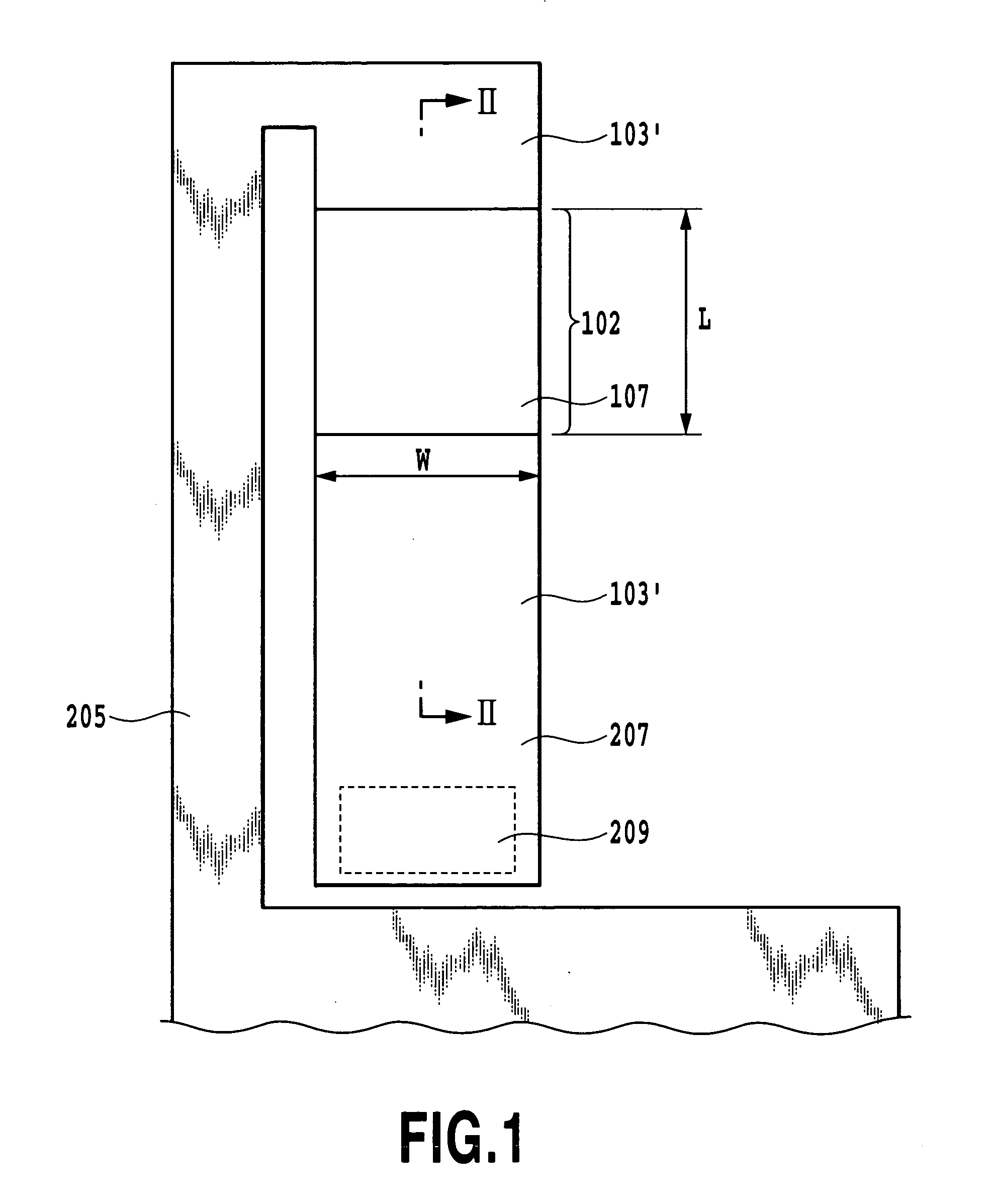
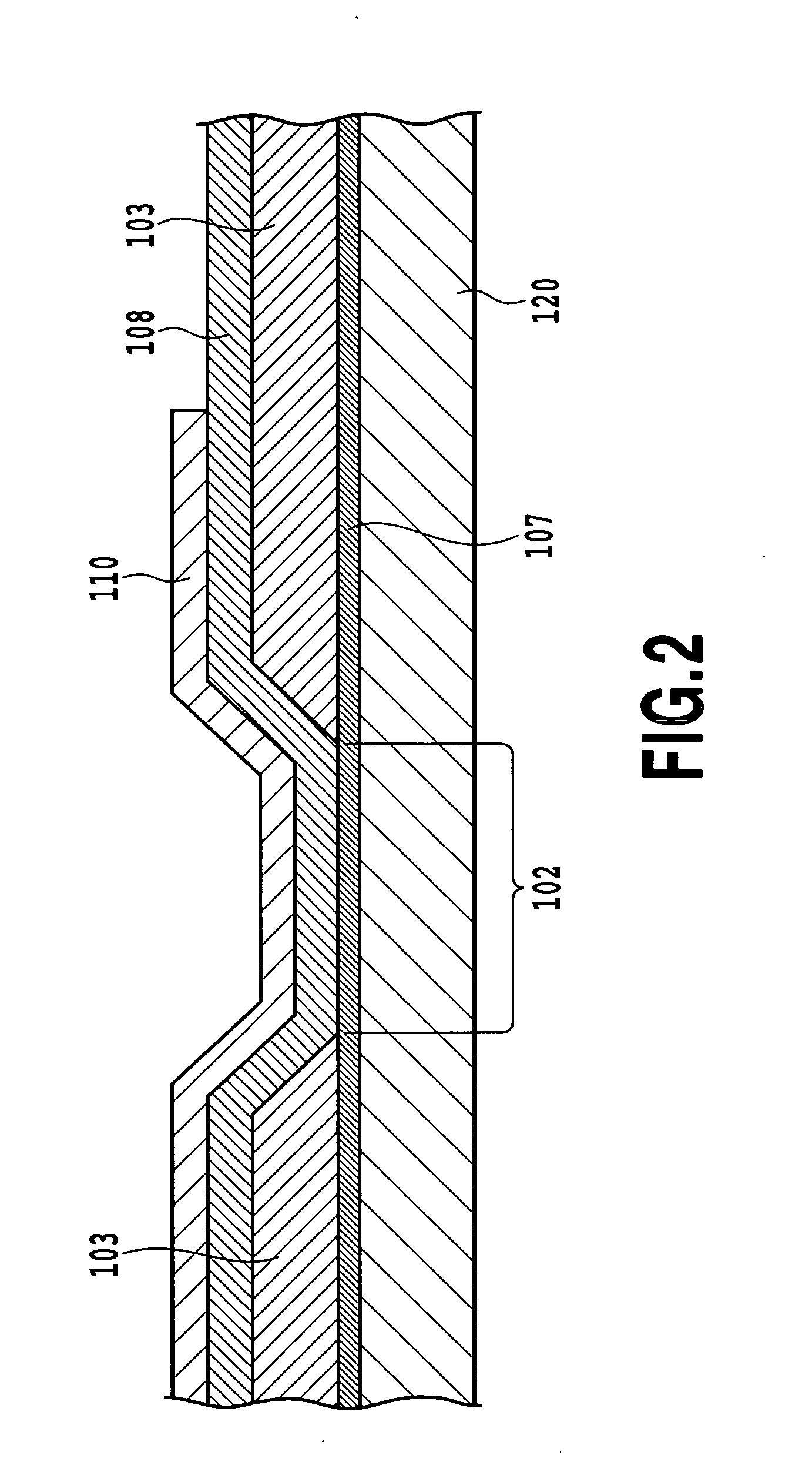
[0050]FIG. 4 is a schematic cross-sectional view of a heater in an ink jet head circuit board according to the first embodiment of the invention, taken along the line II-II of FIG. 1. In this figure, components that function in the same way as those in FIG. 2 are given like reference numbers.

[0051] In this embodiment, as shown in FIG. 4, a pair of electrodes 101 spaced a desired distance apart are placed on a substrate 120 through an insulation layer 106. The electrodes 101 are made of a corrosion resistant metal. Over the electrodes 101 is deposited an electrode wire layer 103 made of aluminum or an alloy containing aluminum which has a gap wider than the gap of the electrodes 101. The electrode wire layer 103 is electrically connected to the electrode wires 101. A resistor layer 107 is deposited over these layers. That is, a heater 102 is formed in the gap of the electrodes 101 and its di...


PUM


Abstract

An ink jet head circuit board is provided which has heaters to generate thermal energy for ink ejection. This board has the heaters formed with high precision to reduce their areas. It has provisions to protect the electrode wires against corrosion and prevent a progress of corrosion. The substrate is deposited with the thin first electrodes made of a corrosion resistant metal. Over the first electrodes the second electrodes made of aluminum are formed. The second electrodes are deposited with a resistor layer. The heater is formed in the gap between the first electrodes. With this construction, the heaters are formed without large dimensional variations among them. Should a defect occur in a protective layer above or near the heaters, a progress of corrosion can effectively be prevented because the material of the resistor layer is more resistant to encroachment than aluminum and the first electrodes are corrosion resistant.

Description

BACKGROUND OF THE INVENTION [0001] 1. Field of the Invention [0002] The present invention relates to a circuit board for an ink jet head that ejects ink for printing, a method of manufacturing the circuit board, and an ink jet head using the circuit board. [0003] 2. Description of the Related Art [0004] An ink jet printing system has an advantage of low running cost because an ink jet head as a printing means can easily be reduced in size, print a high-resolution image at high speed and even form an image on so-called plain paper that is not given any particular treatment. Other advantages include low noise that is achieved by a non-impact printing system employed by the print head and an ability of the print head to easily perform color printing using multiple color inks. [0005] There are a variety of ejection methods available for the ink jet head to realize the ink jet printing system. Among others, ink jet heads using thermal energy to eject ink, such as those disclosed in U.S. ...

Claims


Application Information

Patent Timeline
Patent Type & Authority Applications(United States)
IPC IPC(8): B41J2/04B41J2/05
CPCB41J2/14072B41J2/1628B41J2/1603B41J2/14129B41J2/1629
Inventor SHIBATA, KAZUAKIYOKOYAMA, SAKAIONO, KENJIOZAKI, TERUOIBE, SATOSHISAITO, ICHIROSAKAI, TOSHIYASU
Owner CANON KK
Why Eureka
Try Eureka