Apparatus for forming pattern

Inactive Publication Date: 2006-02-16
ORC MFG
View PDF2 Cites 8 Cited by
  • Summary
  • Abstract
  • Description
  • Claims
  • Application Information

AI Technical Summary

Benefits of technology

[0008] An object of the present invention is to provide an apparatus and method for forming a pattern that is capable of precisely forming a pattern or patterns in layers on a substrate, regardless of a construction of a light-modulating unit such as a DMD.

Problems solved by technology

In the manufacturing process of the substrate, the substrate occasionally deforms due to the heating process.
Further, when forming patterns in layers on the substrate by using the exposure unit, the positioning precision is not sufficient, so that a position-error, such as a rotation-error or shift-error, is caused in each pattern.

Method used


Image

  • Apparatus for forming pattern
  • Apparatus for forming pattern
  • Apparatus for forming pattern

Examples


Embodiment Construction

[0020] Hereinafter, the preferred embodiment of the present invention is described with reference to the attached drawings.

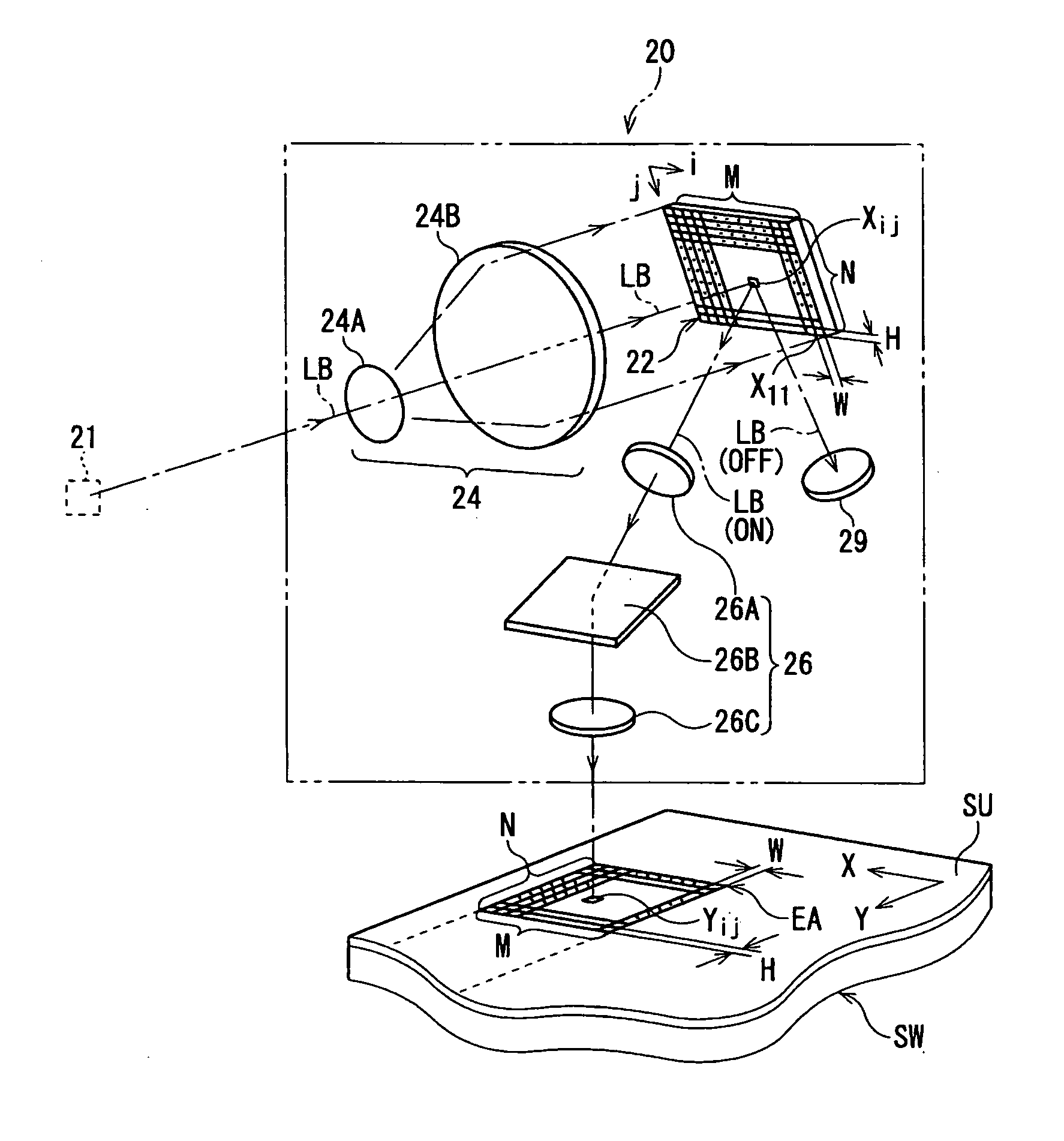
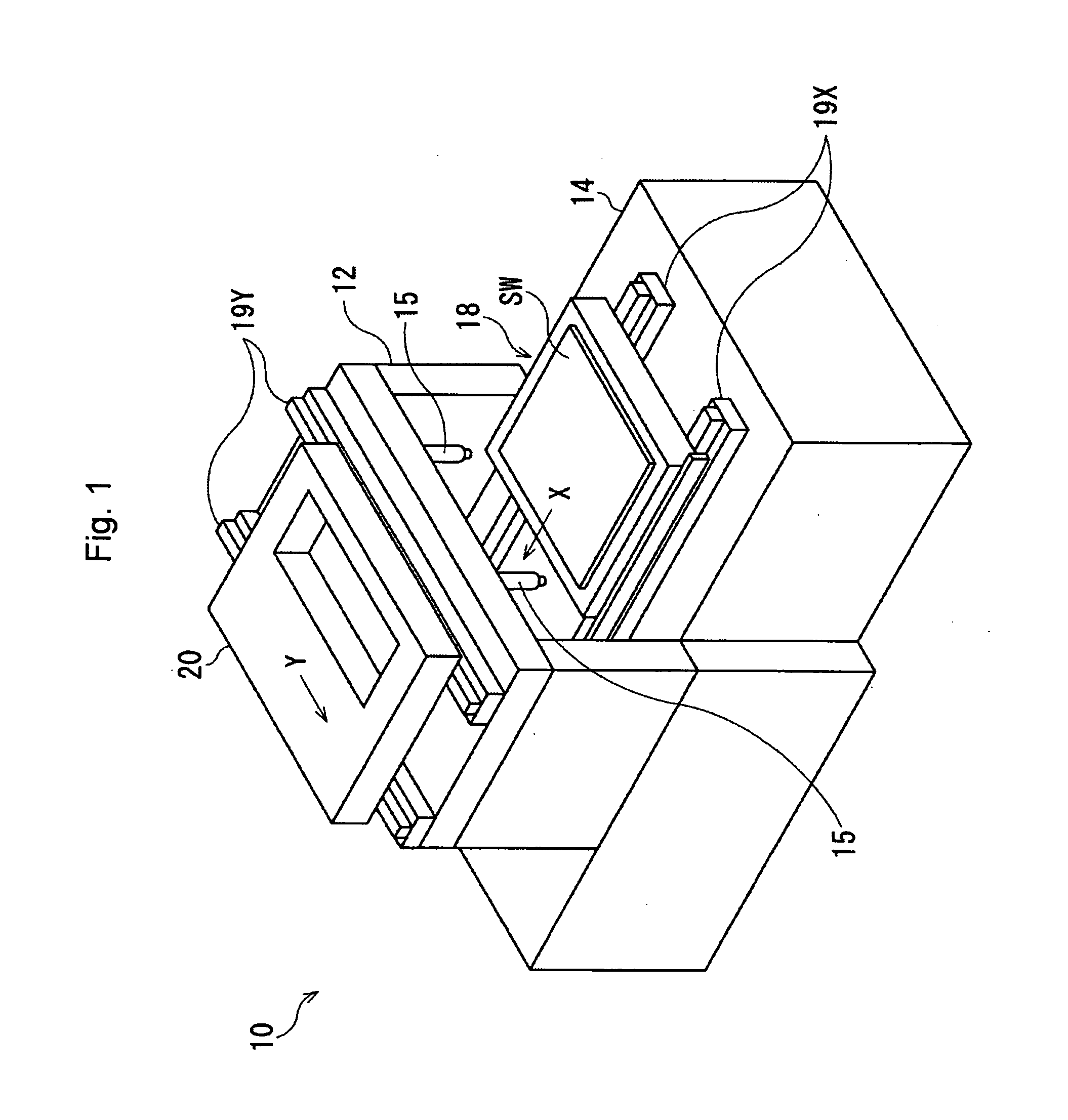
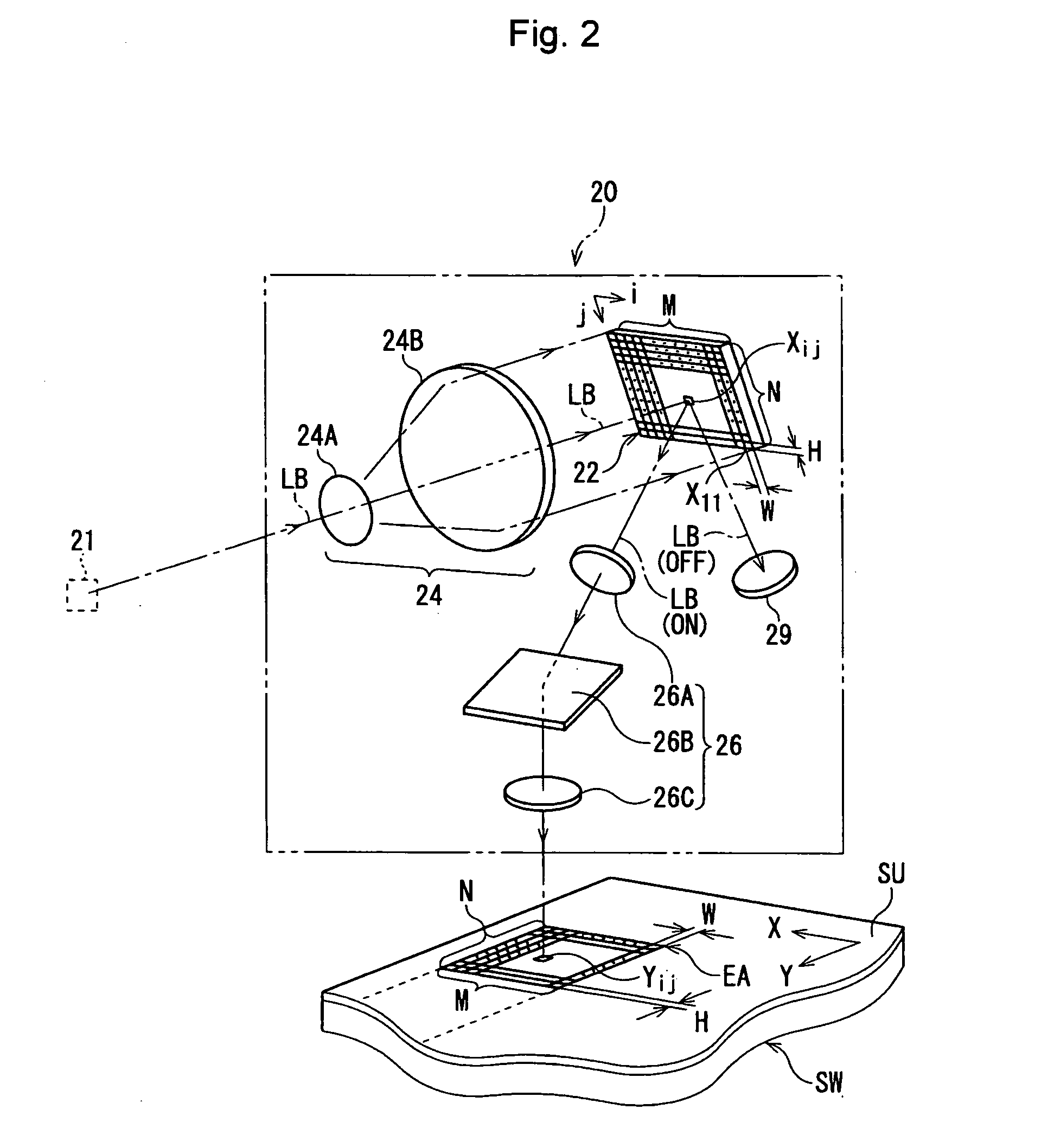
[0021]FIG. 1 is a schematic perspective view of a beam writer according to the present embodiment. FIG. 2 is a schematic view of an exposure unit.

[0022] A beam writer 10 that performs a raster-scanning while continuously moving a table 18, has a gate member 12 and a base 14. A substrate SW is put on the table 18, and the table 18 is supported by guide rails 19X, which are parallel to each other. The guide rails 19X are put on the base 14, and the table 18 is capable of moving along the guide rails 19X. Guide rails 19Y, which are parallel to each other and support an exposure unit 20, is put on the gate member 12. The exposure unit 20 is capable of moving along the pair of guide rails 19Y.

[0023] A moving direction of the table 18 (hereinafter, designated as “X-direction”) is perpendicular to a moving direction of the exposure unit 20 (hereinafter, designated a...


PUM


Abstract

An apparatus for forming a pattern has a light-modulating unit, a scanner, a pattern data processor, a light modulating controller, a position-error detector, and a correction value calculator. The pattern data processor generates band-pattern data corresponding to each scanning band on the basis of pattern data matching a preceding pattern that is repeatedly and regularly formed on the photo-sensitive material. The position-error detector detects a position-error of the preceding pattern relative to a pattern area. The correction value calculator calculates an alignment correction value in each pattern area on the basis of the position-error, so as to overlay the pattern on the preceding pattern. The pattern data processor corrects the band-pattern data in accordance with the alignment correction value while classifying each exposure data of the band-pattern data into a corresponding pattern area.

Description

BACKGROUND OF THE INVENTION [0001] 1. Field of the Invention [0002] The present invention relates to an apparatus and method that directly writes or forms a pattern on a photosensitive material such as a substrate, especially, it relates to the positioning of the pattern. [0003] 2. Description of the Related Art [0004] An exposure unit with a photolithography function transfers a circuit pattern to a substrate by using a photo-mask or reticle to repeatedly and regularly form a circuit pattern on the total area of a substrate. In the exposure unit, a shot-exposure is repeatedly performed in accordance with the Step & Repeat method. Further, a beam writer that directly writes or forms a pattern without a photo-mask / reticle is also applied. In this case, a light-modulating unit such as a DMD (Digital Micro-mirror Device) or an LCD (Liquid Crystal Device), which has two-dimensionally arrayed light-modulator elements, is utilized instead of a line-scanning. [0005] In the manufacturing pr...

Claims


Application Information

Patent Timeline
IPC IPC(8): G03B27/42
CPCG03B27/42
Inventor OKUYAMA, TAKASHI
Owner ORC MFG
Why Eureka
Try Eureka