

Solid oxide fuel cell
a fuel cell and solid oxide technology, applied in the field of solid oxide fuel cell systems, can solve the problems of irregularity of electric power generation due to the temperature distribution at each cell or the inability to reduce the temperature of the module sufficiently, and the performance of the anode made with the fe/ysz cermet is inferior to the case, etc., to achieve the effect of low operation temperature and high operation temperatur
- Summary
- Abstract
- Description
- Claims
- Application Information
AI Technical Summary
Benefits of technology
Problems solved by technology
Method used
Image

Examples
first embodiment
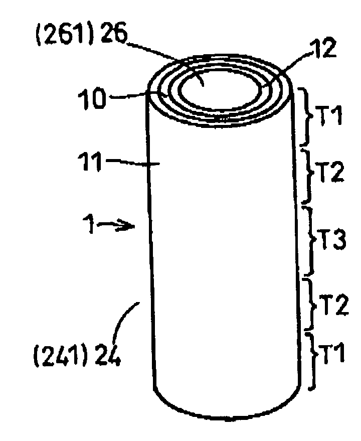
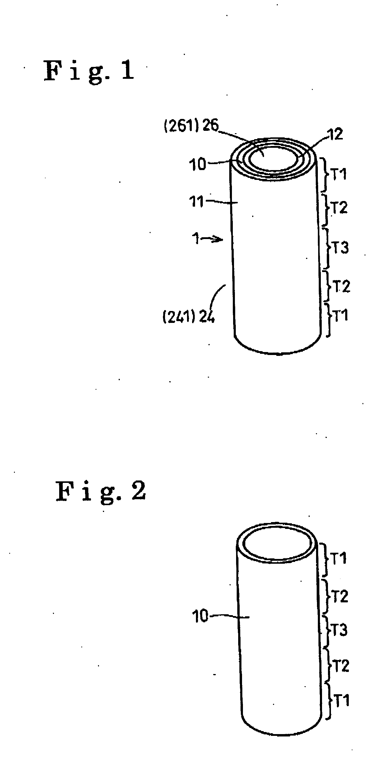
[0095] a solid oxide electrolyte fuel system will be explained with reference to FIGS. 1-5 as follows. A cell 1 according to the solid oxide electrolyte fuel system includes a cylindrical solid oxide electrolyte 10 exhibiting the ion condition, a cylindrical porous anode 11 provided on a one side (external peripheral side) in the thickness direction of the solid oxide electrolyte 10, and a cylindrical porous cathode 12 provided on the other side (internal peripheral side) in the thickness direction of the solid oxide electrolyte 10.
[0096] As shown in FIGS. 1-2, the central region in the axially longitudinal direction of the solid oxide electrolyte 10 is determined to be the high temperature region T3 (e.g., 900-1100° C.). End regions in the axial direction of the solid oxide electrolyte 10 are determined to be the low temperature region T1 (e.g., equal to or greater than 500° C. less than 700° C.). The intermediate temperature region T2 (e.g., greater than 700° C. less than 900° C.)...
second embodiment
[0112] the present invention will be explained with reference to FIGS. 6-8. As shown in FIG. 6a and 6b, a rectangular plate shaped cell1B applied to the solid oxide fuel cell system of the embodiment includes a plate configured solid oxide electrolyte 10B having the oxygen ion conduction, an rectangular plate configured anode 11B provided on one side (one surface side) of the solid oxide electrolyte 10B, and a rectangular plate configured cathode 12B provided on the other side (other one side surface) of the solid oxide electrolyte 10B. The central region of the solid oxide electrolyte 10B is determined to be the high temperature region T3 (e.g., equal to or higher than 900° C. and less than 1100° C.). A periphery of the solid oxide electrolyte 10B is determined to be the low temperature region T1 (e.g., equal to or higher than 500° C. and less than 700° C.). The intermediate temperature region T2 (e.g., equal to or higher than 700° C. and less than 900° C.) is positioned between th...
third embodiment
[0128] As shown in FIG. 10, the solid oxide fuel cell system of the third embodiment includes the solid oxide electrolyte 10C, the cell 1C including the anode 11C and the cathode 12C, a fuel supply passage 24C configured to supply the fuel (e.g., hydrocarbon system gas) to the anode 11C of the cell 1C, a first inter-connector 34C extended in the height direction along the anode 11C, and a second inter-connector 35C extended in the height direction along the cathode 12C.
[0129] As shown in FIG. 9, the fuel supply passage 24C includes a first fuel supply passage 241C facing the anode 11C of the honeycomb shaped cell 1C, a second fuel supply passage 242C connected to the first fuel supply passage 241C, a third fuel supply passage 243C connected to the second fuel supply passage 242C, and a fourth fuel supply passage 244C connected to the third fuel supply passage 243C.
[0130] As shown in FIG. 9, an air supply passage 26C includes a first air supply passage 261C facing the cathode 12C of...
PUM
 Abstract
Description
Claims
Application Information