Audio coding

Inactive Publication Date: 2006-02-16
KONINKLIJKE PHILIPS ELECTRONICS NV
View PDF18 Cites 11 Cited by
  • Summary
  • Abstract
  • Description
  • Claims
  • Application Information

AI Technical Summary

Benefits of technology

[0012] According to the invention the prior art sinusoidal coding technique is reversed i.e. phase rather than frequency is transmitted. In the decoder, the frequency can be approximately recovered from the quantised phase information using finite differences as an approximation for differentiation. The noise component of the recovered frequency has a pronounced high-frequency behaviour under the assumption that the noise introduced by the phase quantisation is nearly spectrally flat. This is illustrated in FIG. 2(b), where within the encoder and the decoder, frequency is represented as the differential (D) of phase. Again, noise n is introduced in the encoder and so in the decoder, the recovered frequency {circumflex over (Ω)} includes two components: the real frequency Ω and a noise component ε4, where the frequency is nearly a DC signal and the noise is mainly in high-frequency range. However, since the underlying frequency has a low-frequency behaviour and the added noise a high-frequency behaviour, the noise component ε4 of the recovered frequency can be reduced by low-pass filtering.

Problems solved by technology

In contrast to frequency, phase transmission is viewed as expensive.
It is known, however, that the phase can only be approximately recovered using phase continuation.
If frequency errors occur, due to measurement errors in the frequency or due to quantisation noise, the phase, being reconstructed using the integral relation, will typically show an error having the character of a drift.
Integration amplifies low-frequency errors and, consequently, the recovered phase will tend to drift away from the actually measured phase.
This leads to audible artifacts.
However, the noise introduced in the reconstruction process is also dominant in this low-frequency range.
It is therefore difficult to separate these sources with a view to filtering the noise n introduced during encoding.

Method used


Image

  • Audio coding
  • Audio coding
  • Audio coding

Examples


Embodiment Construction

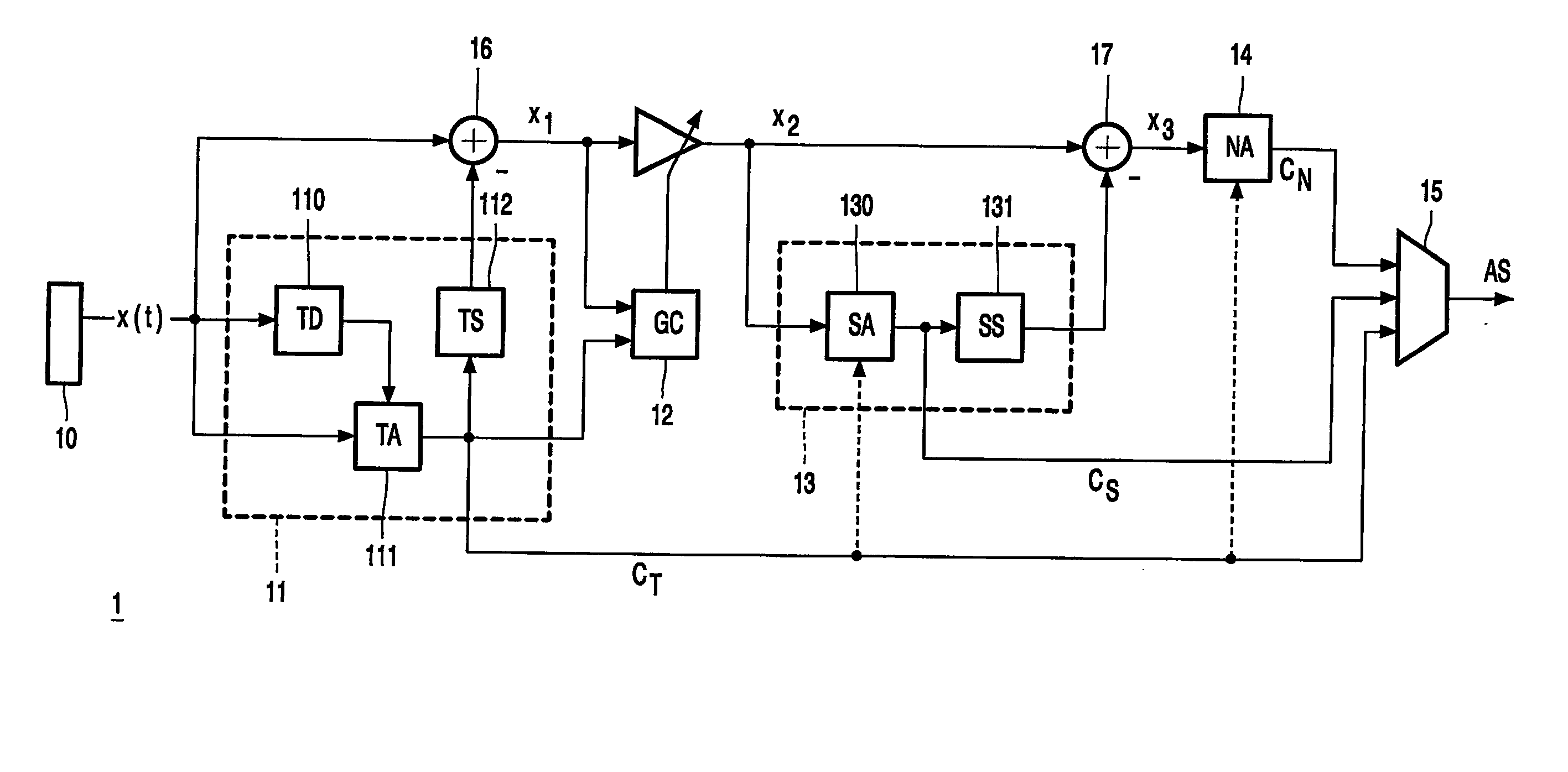
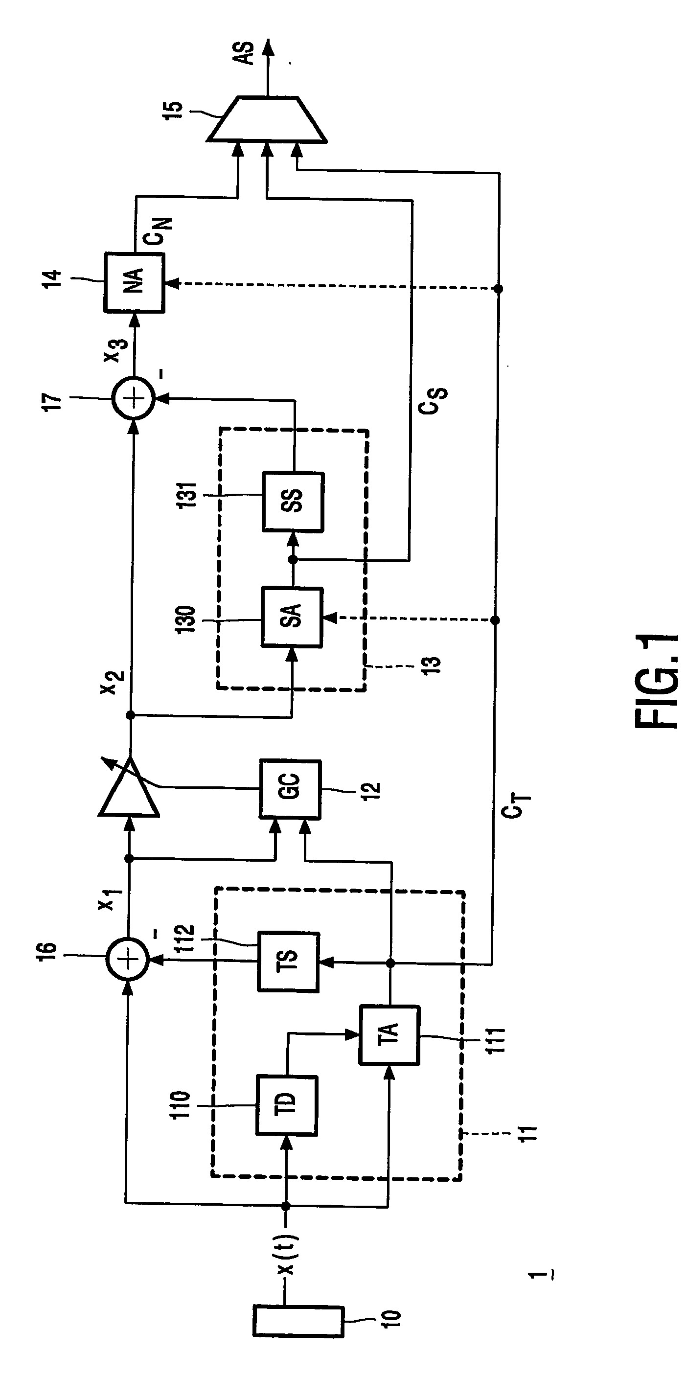
[0019] Preferred embodiments of the invention will now be described with reference to the accompanying drawings wherein like components have been accorded like reference numerals and, unless otherwise stated perform a like function. In a preferred embodiment of the present invention, the encoder 1 is a sinusoidal coder of the type described in PCT Patent Application No. WO 01 / 69593, FIG. 1. The operation of this prior art coder and its corresponding decoder has been well described and description is only provided here where relevant to the present invention.

[0020] In both the prior art and the preferred embodiment, the audio coder 1 samples an input audio signal at a certain sampling frequency resulting in a digital representation x(t) of the audio signal. The coder 1 then separates the sampled input signal into three components: transient signal components, sustained deterministic components, and sustained stochastic components. The audio coder 1 comprises a transient coder 11, a ...


PUM


Abstract

Coding of an audio signal represented by a respective set of sampled signal values for each of a plurality of sequential segments is disclosed. The sampled signal values are analysed (40) to determine one or more sinusoidal components for each of the plurality of sequential segments. The sinusoidal components are linked (42) across a plurality of sequential segments to provide sinusoidal tracks. For each sinusoidal track, a phase comprising a generally monotonically changing value is determined and an encoded audio stream including sinusoidal codes (r) representing said phase is generated (46).

Description

FIELD OF THE INVENTION [0001] The present invention relates to coding and decoding audio signals. BACKGROUND OF THE INVENTION [0002] Referring now to FIG. 1, a parametric coding scheme in particular a sinusoidal coder is described in PCT Patent Application No. WO01 / 69593. In this coder, an input audio signal x(t) is split into several (overlapping) segments or frames, typically of length 20 ms. Each segment is decomposed into transient, sinusoidal and noise components. (It is also possible to derive other components of the input audio signal such as harmonic complexes although these are not relevant for the purposes of the present invention.) [0003] In the sinusoidal analyser 130, the signal x2 for each segment is modelled using a number of sinusoids represented by amplitude, frequency and phase parameters. This information is usually extracted for an analysis interval by performing a Fourier Transform (FT) which provides a spectral representation of the interval including: frequenc...

Claims


Application Information

Patent Timeline
IPC IPC(8): G10L11/04G10L19/08G10L19/093G10L25/90
CPCG10L19/093G10L19/02
Inventor DEN BRINKER, ALBERTUS CORNELISGERRITS, ANDREAS JOHANNESSLUIJTER, ROBERT JOHANNES
Owner KONINKLIJKE PHILIPS ELECTRONICS NV
Why Eureka
Try Eureka