System and method for detecting errors in a network

a network error and network technology, applied in the field of communication networks, can solve the problems of insufficient efficiency, increased difficulty in isolating network errors, and decreased efficiency, and achieve the effects of efficiently and accurately detecting network errors, network errors, and efficient detection and reporting

Inactive Publication Date: 2006-02-16
GOOGLE LLC
View PDF17 Cites 26 Cited by
  • Summary
  • Abstract
  • Description
  • Claims
  • Application Information

AI Technical Summary

Benefits of technology

[0012] It has been discovered that by providing a number of devices on a network configured to monitor areas of a network and provide information to a network status device (e.g., a network analyzer), network errors can be efficiently detected and reported. Accordingly, one aspect of the present invention provides a system and method for efficiently and accurately detecting errors in a network. Devices coupled to a network are configured to determine local network status and transmit the local network status to a network analyzer. The network analyzer is configured to receive the local network status from each device and provide network status for the entire network. The network analyzer is also configured to analyze the collective network status information and report any network errors. The network analyzer is further configured to present the information in a format that allows a user of the network to quickly determine the configuration and status of the network (such as a computer generated graphical representation of the network).

Problems solved by technology

Unfortunately, known techniques of detecting and isolating network errors are not adequate under all circumstances.
However, when a network error occurs in network 100, one or more hosts 102 may be unable to communicate with any device on network 100 (e.g., a fatal error), or communication with other hosts may be possible, but occur with interruption and / or decreased efficiency because of the error (e.g., a non fatal error).
This large number of components spread across various physical locations adds to the difficulty in isolating network errors.
For example, network errors can be associated with network interface cards, communication cables, network switches, hosts, and / or other components associated with a network.
It is not possible to physically inspect the network and all the associated components, and one must rely on other techniques to diagnose network errors.
Generally, a network error goes unnoticed until communication over the network is actually attempted.
Upon attempting communication which involved line 104(e), the attempt would likely result in errors (in this example).
Unfortunately, realizing the error at the time of need (e.g., when communication is attempted) only increases the urgency with which the error must be resolved and the impact of such error (including potentially significant monetary costs).
Another limitation with existing network diagnostic techniques relates to the accessibility of network status information.
This problem is especially present in heterogeneous networks composed of, for example, hosts having different operating systems and / or communicating via different communication protocols.
Further problems with known network diagnostic techniques include the reliance on manual intervention (i.e., a system administrator) to remotely (or locally) perform network diagnostics.
Relying on one to diagnose and analyze network errors can be a time consuming process, which gets more difficult with each resource added to the network.
This can result in imprecise diagnoses of the original error.
However, such a trial and error approach can fail to identify the underlying cause of the error, and can even introduce additional errors.
Finally, all of the problems above are made more difficult the more complex network 100 becomes.
Many of the deficiencies with known techniques of network error isolation and diagnostics are due, in part, to the inability to detect a network error before communication is attempted, the lack of a centralized network reporting system, and the reliance on manual intervention for isolation / diagnostic purposes.

Method used


Image

  • System and method for detecting errors in a network
  • System and method for detecting errors in a network
  • System and method for detecting errors in a network

Examples


Embodiment Construction

Introduction

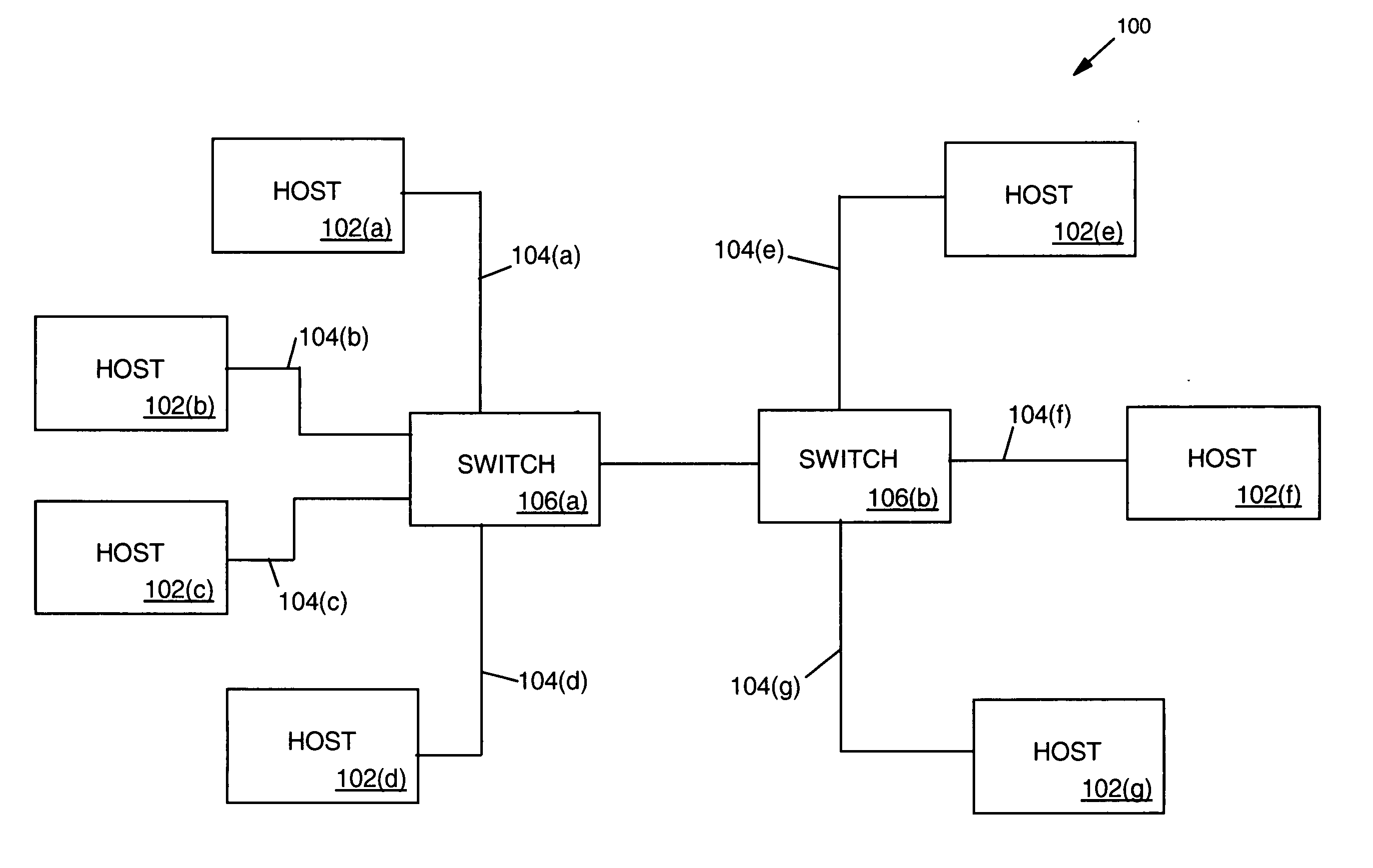
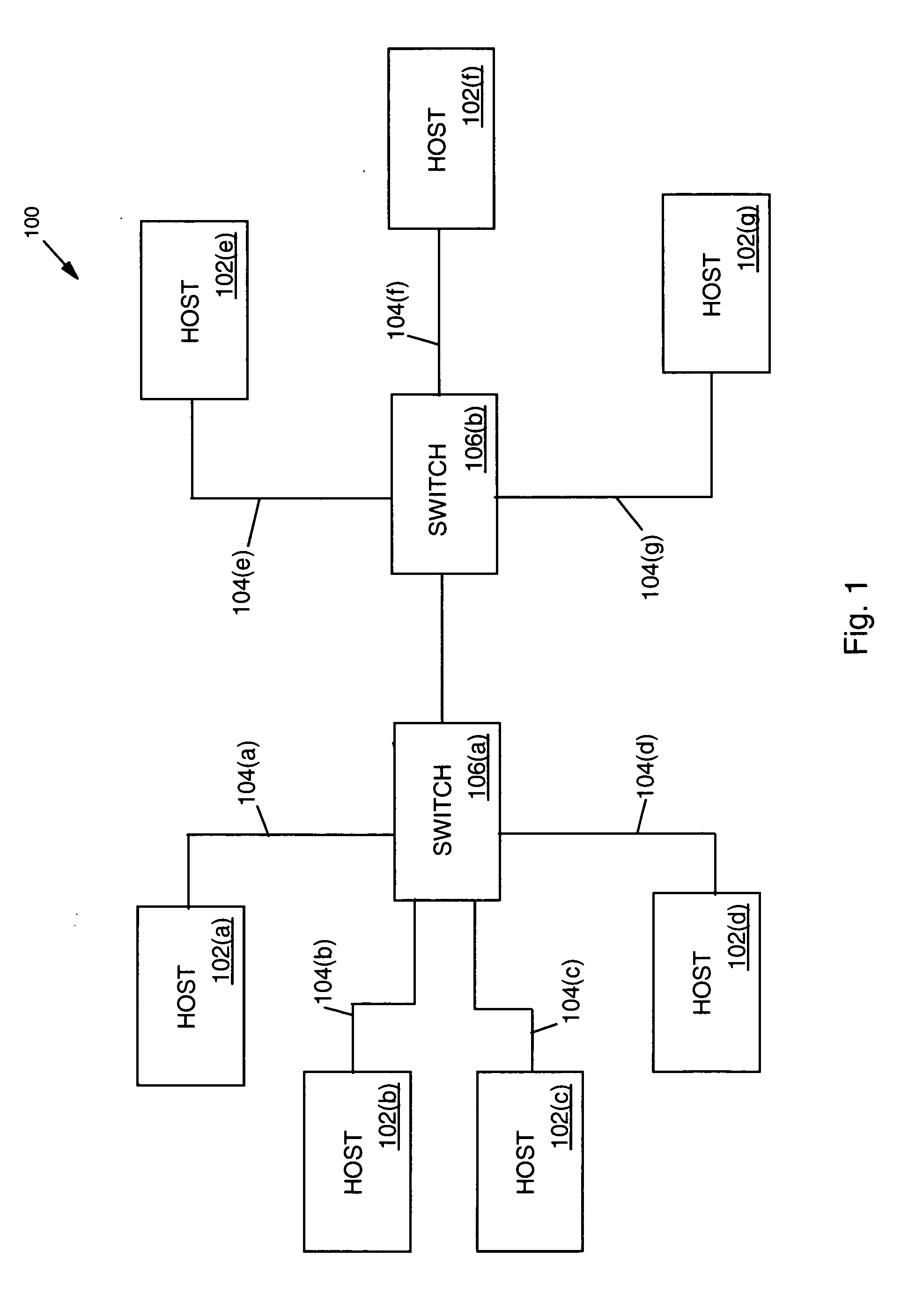
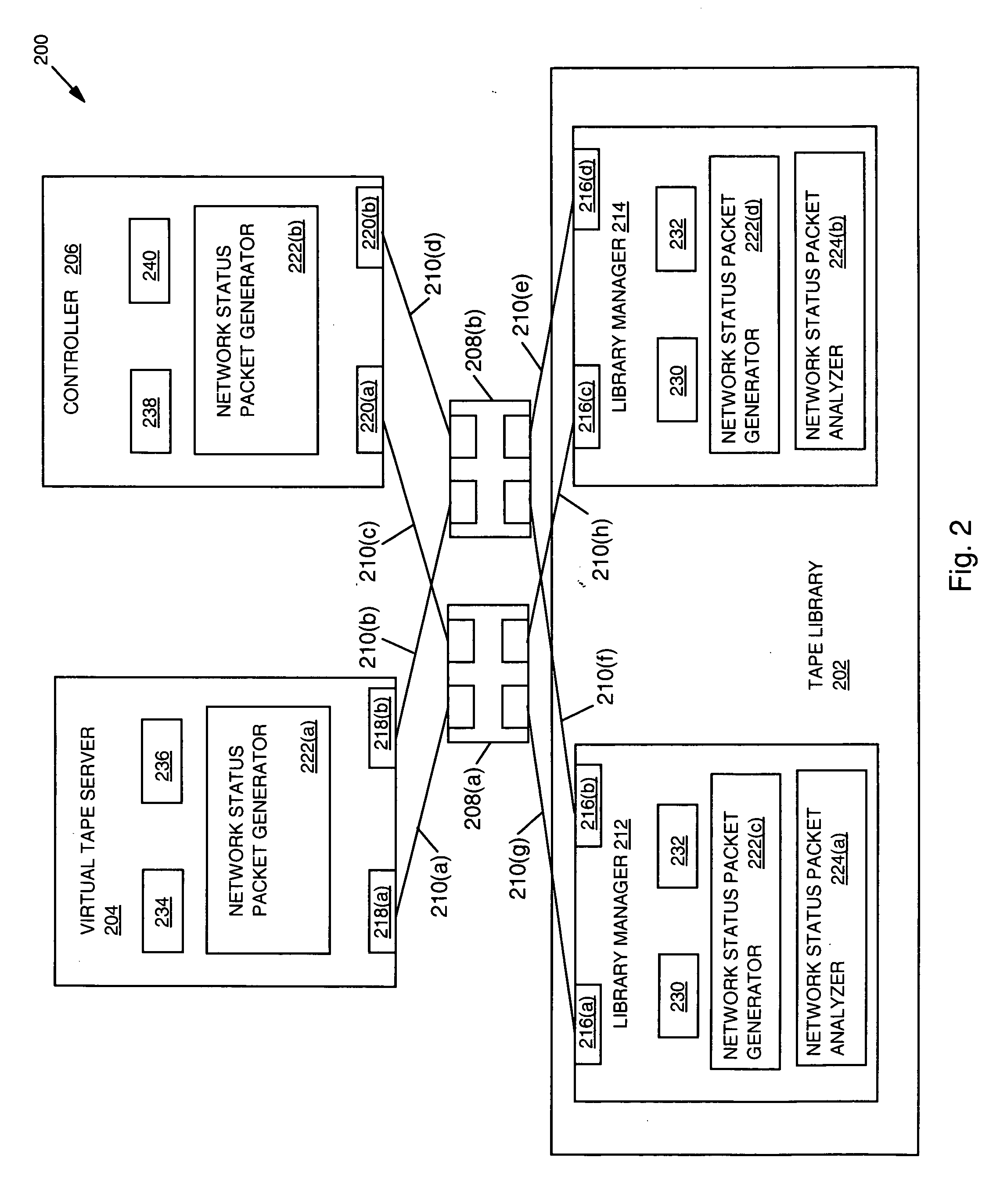
[0019] The detection and isolation of errors in a communication network is crucial to the successful operation of the network. Accordingly, the present invention provides a system and method for efficiently and accurately detecting errors in a network. Explained in greater detail below and in accordance with the present invention, devices coupled to a network are configured to determine their local network status and transmit their local network status to a network analyzer. The network analyzer is configured to receive the local network status from each device and provide network status for the entire network in accordance with the present invention. The network analyzer is also configured to analyze the collective network status information and report any network errors and / or present the information in a format that allows a user of the network to quickly determine the configuration and status of the network (such as a computer generated graphical representation of ...


PUM


Abstract

A system and method for efficiently and accurately detecting errors in a network is provided. Devices coupled to a network are configured to determine their local network status and transmit their local network status to a centralized location. The centralized location is configured to receive the local network status from each device and provide network status for the entire network. The centralized location is also configured to analyze the collective network status information and report any network errors. The centralized location is further configured to present the information in a format that allows a user of the network to quickly determine the configuration and status of the network (such as a computer generated graphical representation of the network).

Description

BACKGROUND [0001] 1. Technical Field [0002] The present invention relates to communication networks, and more specifically to a system and method for detecting errors and / or providing communication status in a communication network. [0003] 2. Description of the Related Art [0004] A communication network is essentially a group of two or more devices configured to communicate with each other and / or exchange data with each other. The successful operation of a communication network depends on the ability of the devices coupled to the network to communicate with each other without error. If errors do occur, successful operation of the network then depends on the expedient resolution of those errors. [0005] Unfortunately, known techniques of detecting and isolating network errors are not adequate under all circumstances. As an aid to understanding some limitations of known techniques, a diagram of a typical network is provided. FIG. 1 is a block diagram of one type of communication networ...

Claims


Application Information

Patent Timeline
Patent Type & Authority Applications(United States)
IPC IPC(8): G06F11/00
CPCH04L41/0659H04L43/0817H04L41/142
Inventor LUCIANI, DAVIDJAMES, RAYMOND ANTHONYTRAVIS, WILLIAM HENRY
Owner GOOGLE LLC
Why Eureka
Try Eureka