Shear transfer plate

a transfer plate and transfer plate technology, applied in the field of improved connection, can solve the problems of ineffective resistance to uplift, failure of the sill, and inability to resist uplift, and achieve the effects of less expensive, enhanced ductility of the bottom strut connection, and greater deformation

Inactive Publication Date: 2006-02-23
SIMPSON STRONG TIE
View PDF79 Cites 50 Cited by
  • Summary
  • Abstract
  • Description
  • Claims
  • Application Information

AI Technical Summary

Benefits of technology

[0009] The present invention improves on prior art modular shearwalls by eliminating foundation bolts and allowing anchor bolts to act not only as uplift anchors but also as shear anchors. Eliminating the additional bolts that are embedded in the concrete foundation speeds installation, making it less expensive. Combined with a direct shear connection between the anchor bolts and the bottom strut, and...

Problems solved by technology

When uplift forces act on a post or stud, these end grain nail connections offer no meaningful resistance to this uplift.
Even if toe nails are used to secure the posts or stud to the bottom sill plate, these are so ineffective at resisting uplift that they are not considered as load paths for uplift forces.
Because the uplift at the sheathing comes in at the side of the sill, and the foundation bolts are in the center of the sill, cross-grain bending of the sill is created, which stresses the wood perpendicular to the grain, and failure of the sill often occurs because wood is so weak when loaded this way.
This does little to enhance the ...

Method used


Image

  • Shear transfer plate
  • Shear transfer plate
  • Shear transfer plate

Examples


Embodiment Construction

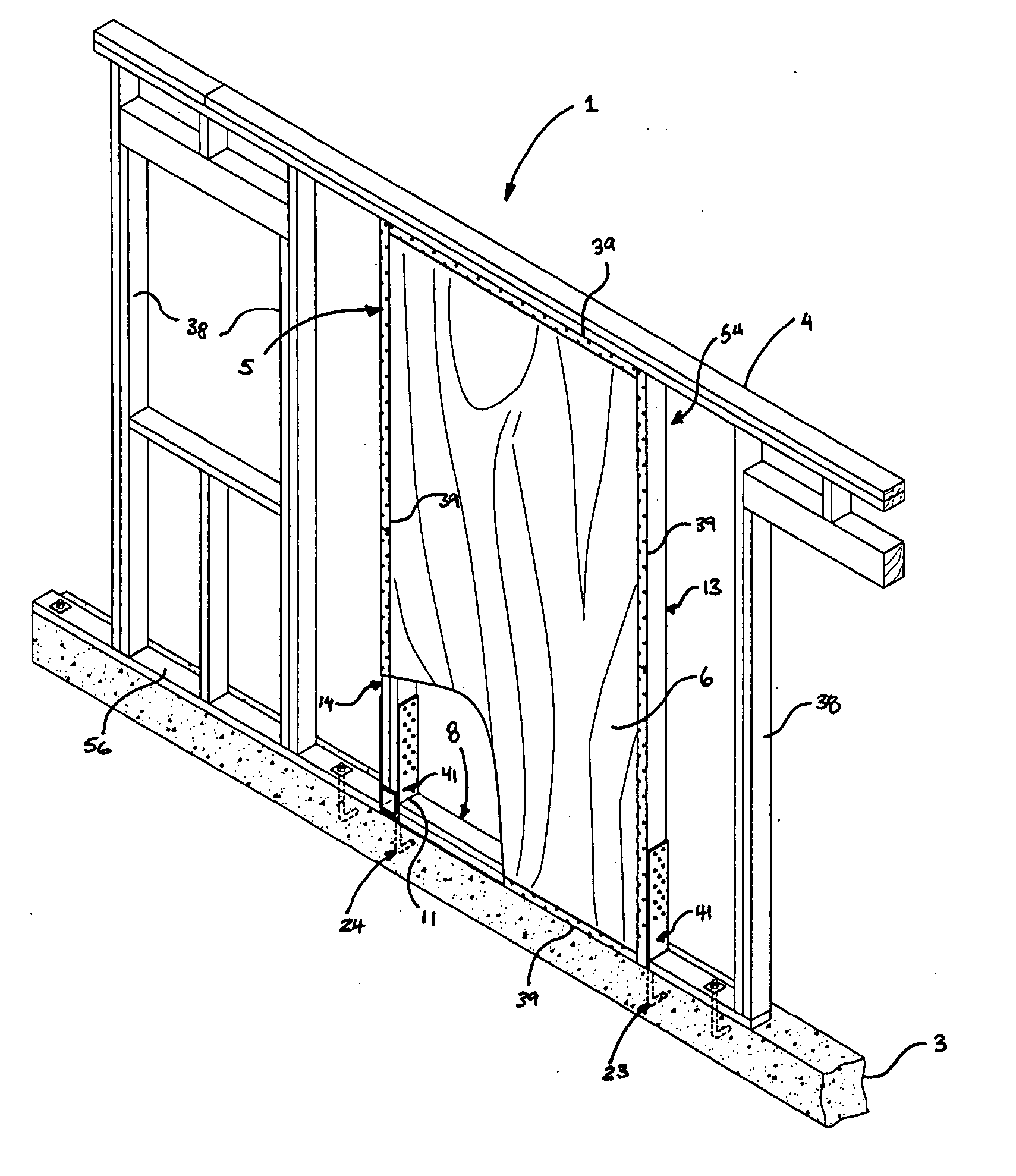
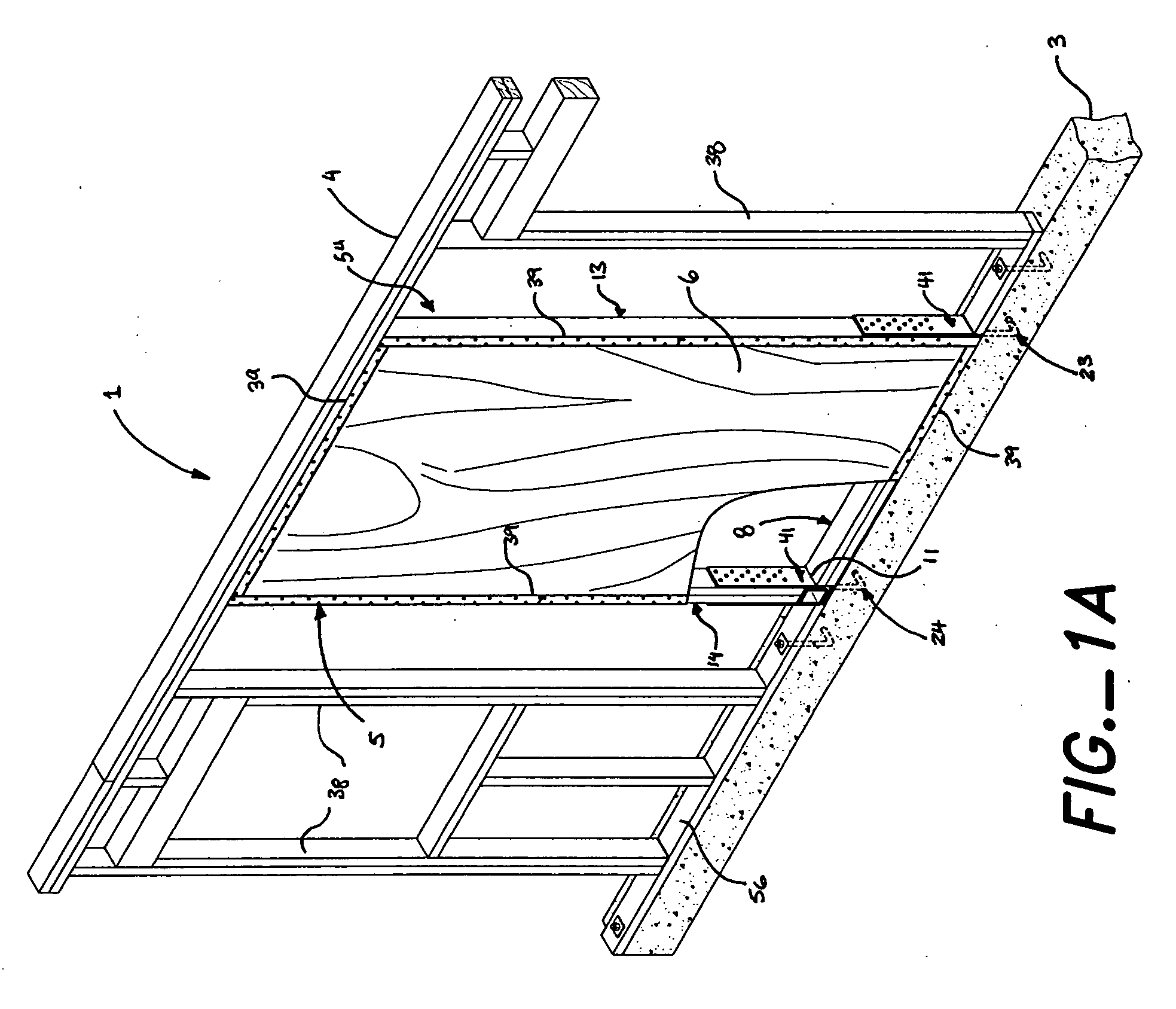
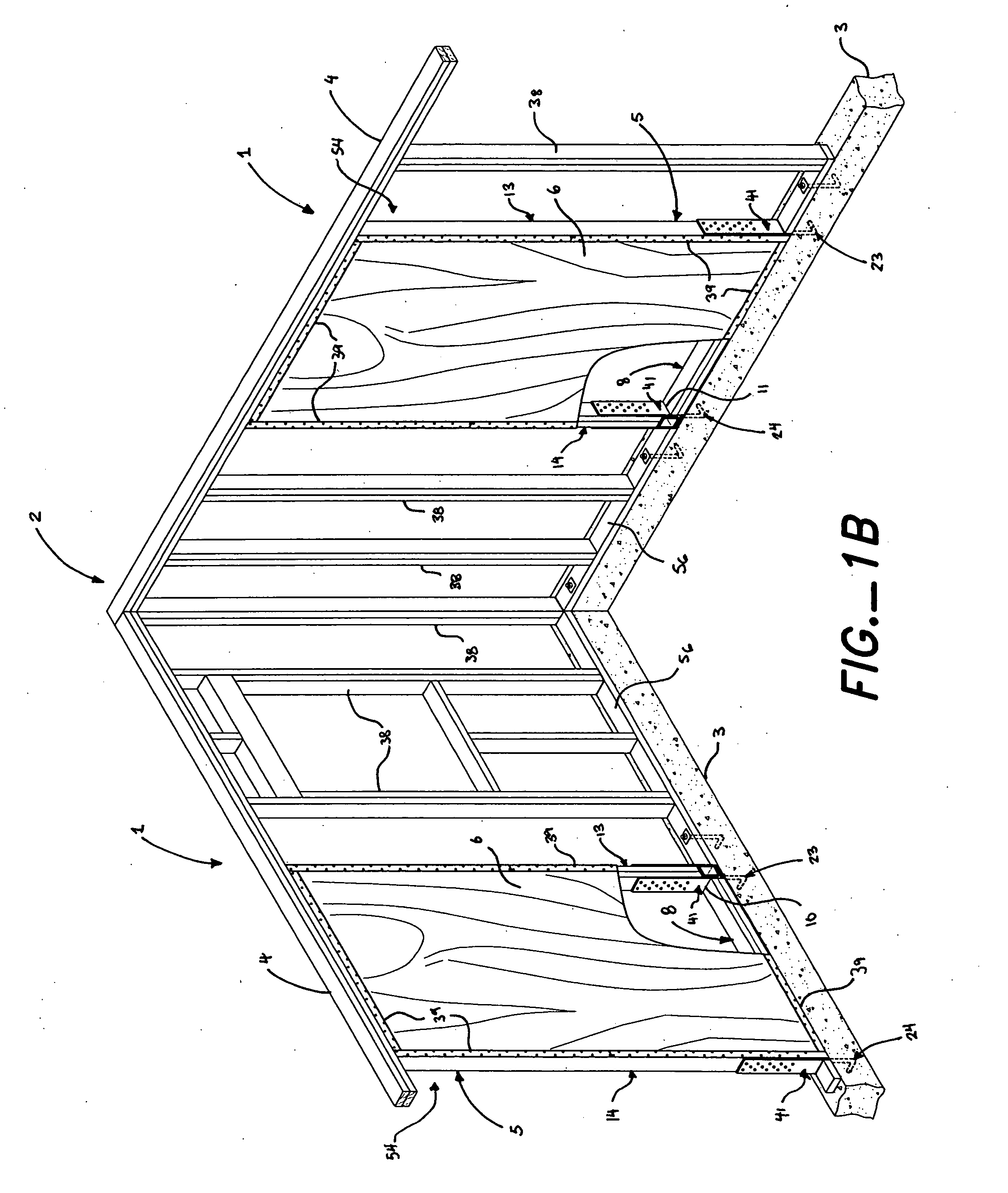
[0058] As best shown in FIGS. 1A and 1B, preferably, the present invention is a wall 1 designed to resist lateral forces imposed on a building 2 incorporating that wall 1. The building 2 has an underlying structural component 3 supporting the wall 1 and a generally horizontal structural member 4, through which lateral shear forces are transmitted, surmounting the wall 1.

[0059] The wall 1 is typically a light wood-frame wall 1 in a light wood-frame building 2, but it could also be light-gauge steel, which is increasingly common particularly in areas where the cost of wood is high, either because the wood must be imported or because local weather conditions increase the cost of maintenance of wood-frame structures. Other structural materials are also possible. Lateral forces are typically those exerted by high winds or earthquakes, the former tending to be fairly consistent in the amount of force and its direction, the latter tending to be stronger, cyclical, and reversing direction....


PUM


Abstract

A wall either wholly or partially made from a shear-resisting assembly that has a shear transfer device, or plate, disposed between the bottom strut and the underlying foundation. The shear transfer device joins the two anchor bolts, eliminating intermediate foundation bolts by transferring lateral shear loads to the anchor bolts in combination with the bottom strut

Description

BACKGROUND OF THE INVENTION [0001] The present invention relates to an improved connection between a wall for resisting lateral forces imposed on a building and the foundation of that building. Specifically, the present invention relates to a shear transfer plate that enhances the transfer of lateral shear forces acting on a wall in a light frame building from the wall into anchor bolts embedded in the concrete foundation. The shear transfer plate is preferably part of a preassembled or prefabricated unitary shearwall subcomponent of the wall, but it can be part of a shearwall that is built on site. The shearwall can be a subcomponent of the wall or it can be the entire wall, commonly created simply by sheathing the wall framing members with plywood, oriented strand board (OSB) or the like. The framing members are typically wood, but light metal framing is now fairly common in some parts of the United States. Whether a subcomponent of a wall, or the entire wall, a shearwall is desig...

Claims


Application Information

Patent Timeline
IPC IPC(8): E04H9/02
CPCE04B2/707E04B2001/2684F16B15/0046E04H9/14E04B2001/2696Y02A50/00
Inventor PRYOR, STEVEN E.
Owner SIMPSON STRONG TIE
Why Eureka
Try Eureka