Self-contained integrated welder/generator and compressor

a welder/generator, self-contained technology, applied in the direction of machines/engines, mechanical equipment, manufacturing tools, etc., can solve the problems of reducing the available power for other power tools, affecting the service life of the compressor, so as to achieve convenient operation and maintenance, convenient transportation

a welder/generator, self-contained technology, applied in the direction of machines/engines, mechanical equipment, manufacturing tools, etc., can solve the problems of reducing the available power for other power tools, affecting the service life of the compressor, so as to achieve convenient operation and maintenance, convenient transportation

US20060037954A1Inactive Publication Date: 2006-02-23LINCOLN GLOBAL INC

Image

  • Self-contained integrated welder/generator and compressor
  • Self-contained integrated welder/generator and compressor
  • Self-contained integrated welder/generator and compressor

Examples


Embodiment Construction

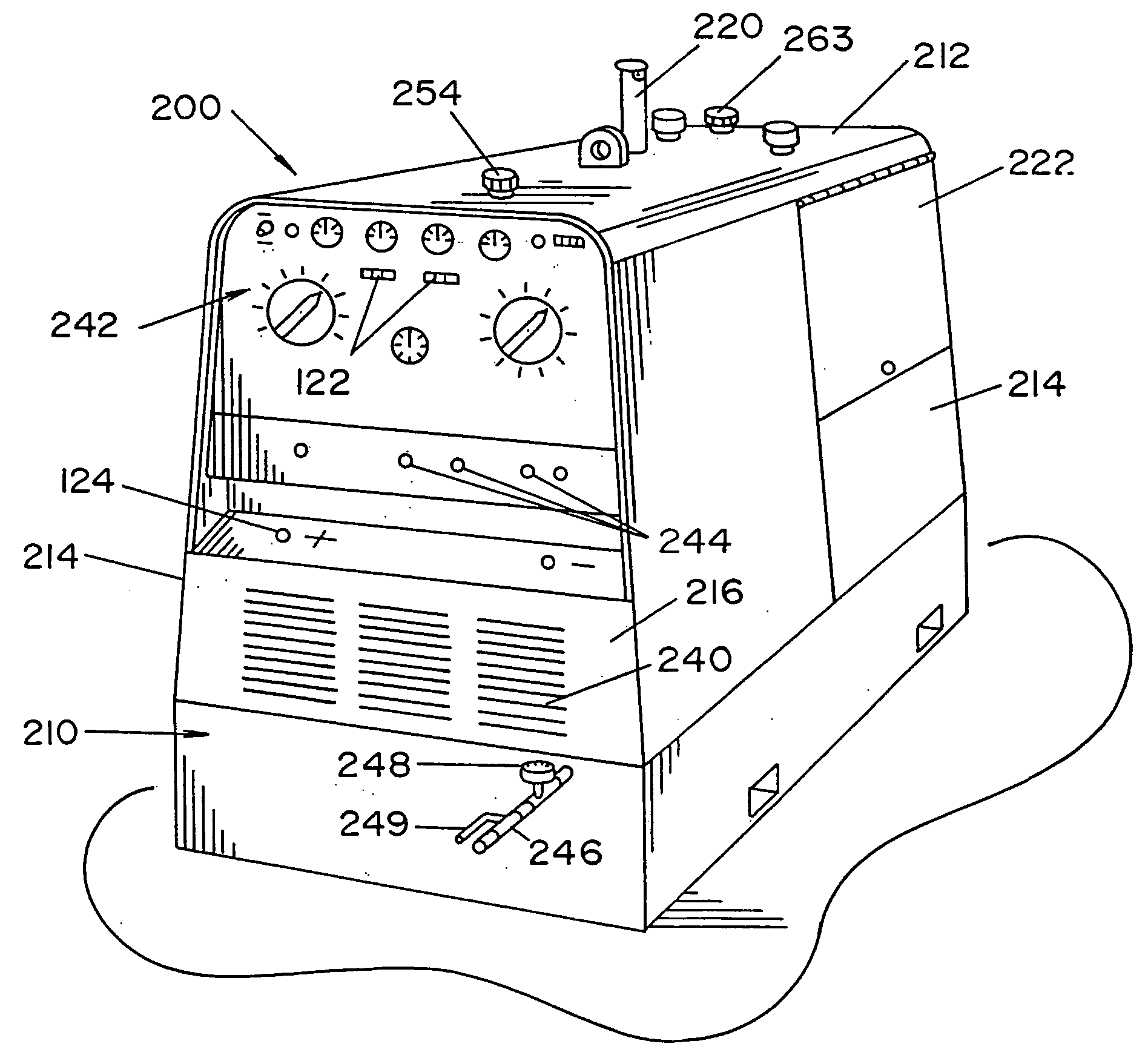
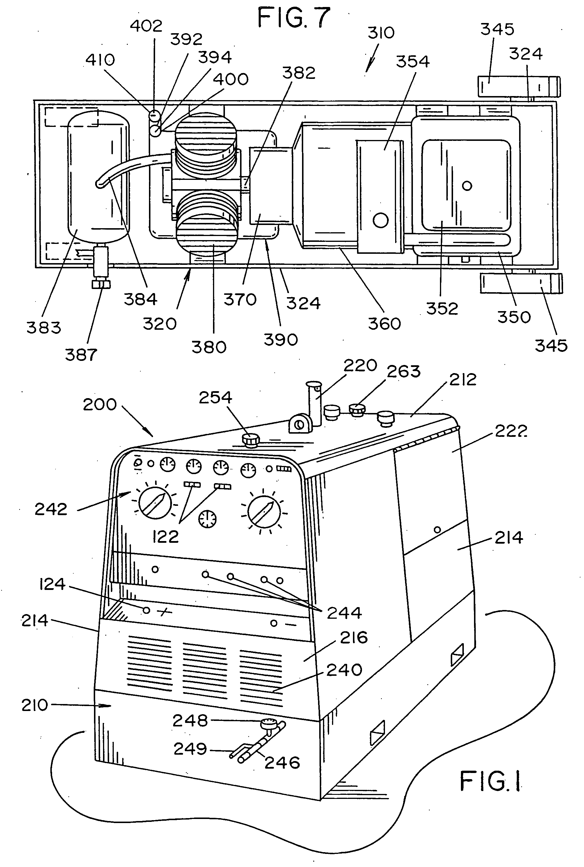
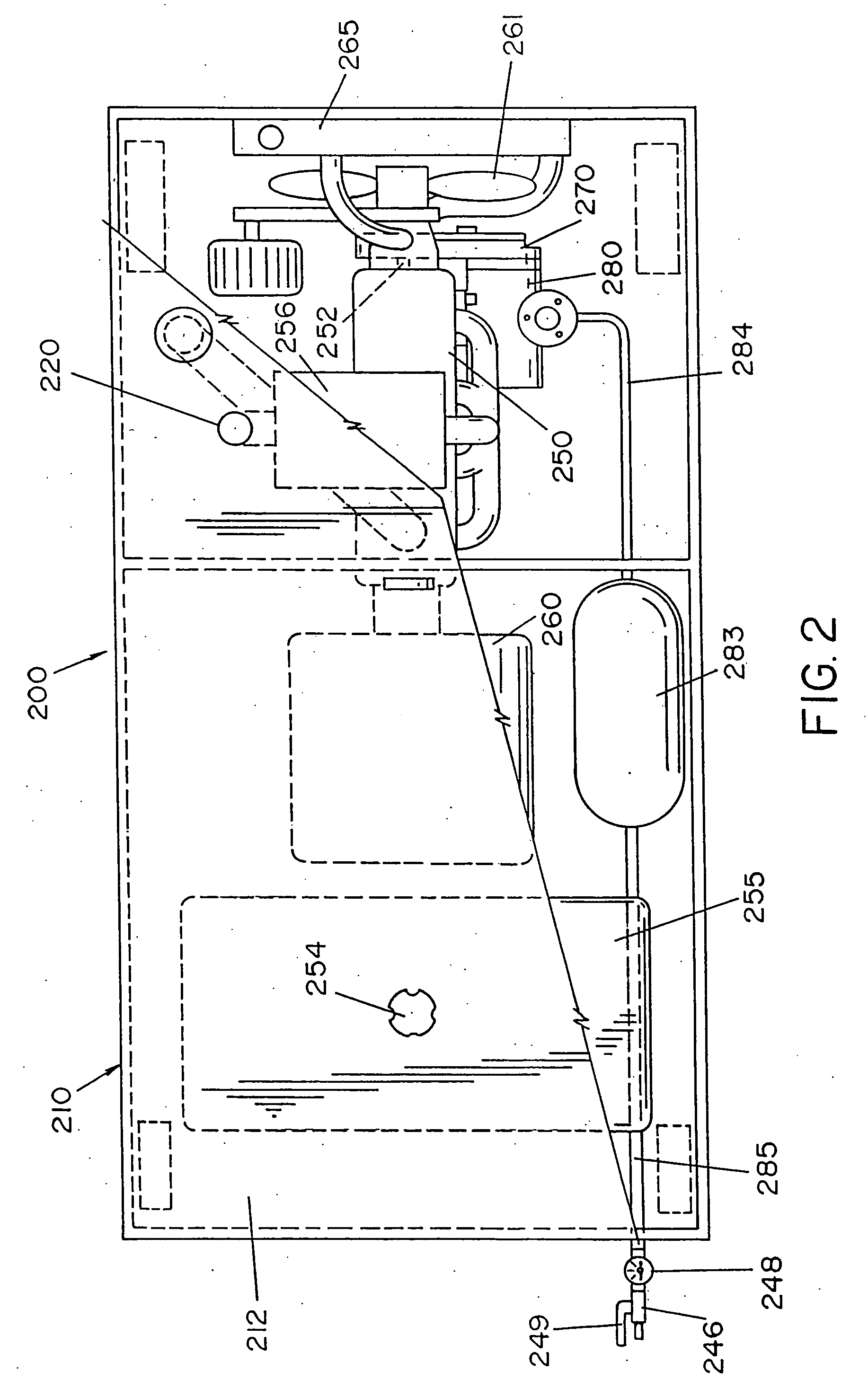
[0025] Referring now to the drawings, wherein the showings are for the purpose of illustrating the preferred embodiments of the invention only and not for the purpose of limiting the same, FIGS. 1-5 illustrate one embodiment of the invention. FIGS. 1 and 2 illustrate a self-contained, portable and fully-integrated welder / generator and compressor unit 200 in accordance with the present invention. Unit 200 includes a housing 210 that has a top portion 212 and two side portions 214. The welding housing is designed to encase at least a portion of the internal components of the engine welder. Positioned in the top portion 212 of welding housing 210 is an exhaust pipe opening 220. A motor access opening 222 is located on one side of housing 210.

[0026] The front face 216 of housing 210 includes a vent 240 to allow air flow within the housing to thereby cool the internal components of the welder / generator and compressor unit. The front face also includes various switches, knobs, indicator ...


PUM

PropertyMeasurementUnit
voltage ratingaaaaaaaaaa

Abstract

An integrated welder, generator and compressor unit that includes a housing that at least partially contains components of a welder, generator and compressor. An engine, an electric current generator, and an air compressor are at least partially mounted in the housing. The electric current generator is at least partially connected to the engine to be at least partially driven thereby. A drive connector at least partially connects the air compressor to the engine and / or electric current generator. The drive connector includes a gear box that has at least one gear.

Description

[0001] The present invention is a continuation of co-pending U.S. patent application Ser. No. 10 / 390,436 filed Mar. 17, 2003.[0002] The present invention relates generally to engine driven welding machines, and more particularly to a welder / generator and compressor unit that can be transported to a site for welding and / or for operating air or electric power tools. BACKGROUND OF THE INVENTION [0003] Engine driven welding machines include a gas powered engine to run a generator which supplies power to the welding electrode. Two such engine welders are disclosed in U.S. Pat. Nos. 6,296,027 and 6,172,332, both of which are incorporated herein by reference. The generator can also be used to operate other electrical equipment (e.g., lights, pumps, etc.). On a construction site, welding equipment and other types of equipment are commonly used. The engine driven welder is commonly used to provide electrical power to electric welders, lights, power tools, etc. Air powered tools are also comm...

Claims


Application Information

Patent Timeline
23 Feb 2006
Publication
US20060037954A1
IPC
B23K9/10; B23K9/073; B23K9/32; F02B63/04; F02B63/06; F02B75/18; F02B75/20
CPC
B23K9/1006; B23K9/32; F02B63/04; F02B2075/1816; F02B63/06; F02B75/20; F02B63/048; B23K37/0294
Inventors
SILVESTRO, NINO