Oscillator circuit for EEPROM high voltage generator

a high-voltage generator and oscillator circuit technology, applied in pulse generators, pulse techniques, instruments, etc., can solve the problem of reducing the life of eeprom cells by a significant amoun

Inactive Publication Date: 2006-02-23
ATMEL CORP
View PDF11 Cites 13 Cited by
  • Summary
  • Abstract
  • Description
  • Claims
  • Application Information

AI Technical Summary

Benefits of technology

[0012] In regard to temperature dependence, the same RC time constant is considered with respect to charging current. The basic transconductance of the transistor devices charging the capacitance is inversely proportional to temperature. Therefore, the charge current produced from these devices has the same characteristic and creates a time constant with an inverse proportionality to temperature. By crafting an oscillator network with a component configuration to take advantage of an RC time constant and by fabricating oscillator components from semiconductor devices, first principles of semiconductor physics are employed to effect the desired characteristics in a charge pump oscillator.

Problems solved by technology

The drawback of having a heightened programming voltage is that the lifetime of EEPROM cells reduces significantly even with a relatively small increase in programming voltage.

Method used


Image

  • Oscillator circuit for EEPROM high voltage generator
  • Oscillator circuit for EEPROM high voltage generator
  • Oscillator circuit for EEPROM high voltage generator

Examples


Embodiment Construction

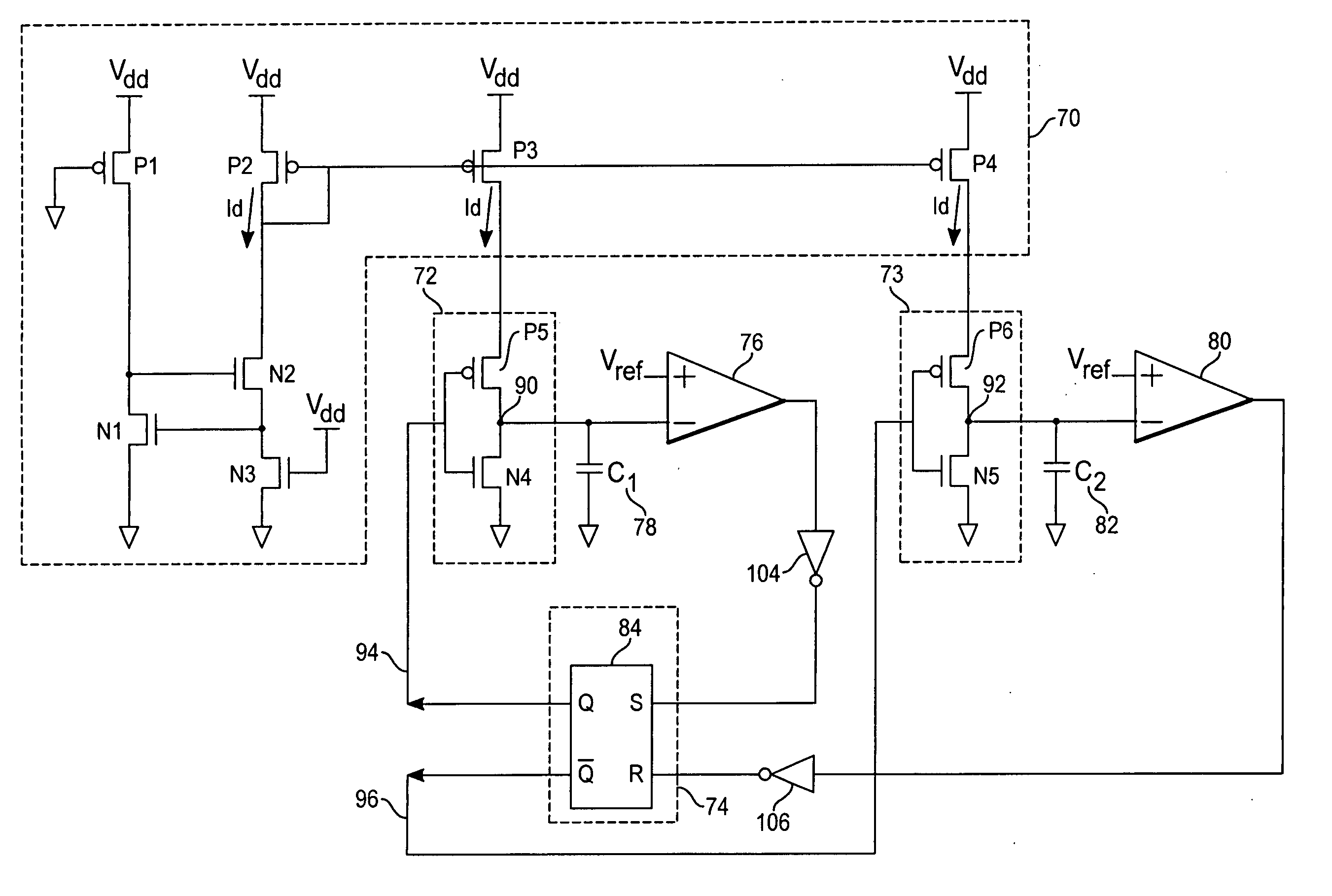
[0018] With reference to FIG. 4, an oscillator circuit according to an exemplary embodiment of the present invention includes five main parts: a current generating means 70 for the production of a current, Id, that is inversely proportional to temperature, a first and a second capacitor 78, 82 connected to the current generator 70 through a first and a second switching means 72, 73, a first and second voltage comparing means 76, 80 connected to the first and second capacitor 78, 82, and a logic means 74 to facilitate the switching of charging current Id to the first and second capacitors 78, 82.

[0019] The current generating means 70 comprises a first PMOS transistor P1 having a source connected to Vdd, a drain connected to a drain of a first NMOS transistor N1 and a gate of a second NMOS transistor N2. The gate of P1 and the drain of N1 connect to ground while the gate of N1 connects to a source of N2 and a drain of a third NMOS transistor N3. A drain of N2 connects to a drain and ...


PUM


Abstract

A semiconductor oscillator circuit for an EEPROM high voltage charge pump utilizes a current generating means to charge a first and a second capacitor alternatively. The charging current produced by the current generating means is inversely proportional to the ambient temperature. The charging current is proportional to the supply voltage and consequently, the oscillator frequency output remains constant over a variable voltage supply. Such a constant frequency characteristic makes a low voltage operation possible, but slows down the oscillator frequency as temperature increases. The slowing of oscillator frequency limits the charge pump output voltage and enhances the lifespan of the EEPROM cells.

Description

TECHNICAL FIELD [0001] The present invention relates to an oscillator circuit, and in particular, the present invention relates to semiconductor oscillators for use in charge pump systems. BACKGROUND ART [0002] In a typical non-volatile memory device such as electrically erasable programmable read only memories (EEPROM), a charge pump is needed to generate the high internal programming voltage necessary to achieve electron tunneling during programming steps. The charge pump circuit takes in a low voltage input and generates a high voltage output using multiple voltage pumping stages. [0003]FIG. 1 shows a simple charge pump circuit, which is commonly known as a Dickson charge pump. The Dickson charge pump includes a plurality of diode ladder stages 10 wherein complementary charge pump clock signals 18, 20 are provided to successive stages. Each diode ladder stage 10 comprises a diode 12 and a capacitor 14 connected together. The charge pump circuit operates by passing charges along s...

Claims


Application Information

Patent Timeline
Patent Type & Authority Applications(United States)
IPC IPC(8): H03K3/02G11C5/14H03K4/501
CPCG11C5/145H03K4/502H03K3/0231H02M3/07
Inventor RICARD, STEPHANEMERANDAT, MARCPRATLONG, JEROMEVERGNES, SYLVIE B.BOUR, LAURELINE
Owner ATMEL CORP
Why Eureka
Try Eureka