Exposure method and exposure apparatus

a technology of exposure apparatus and exposure method, which is applied in the direction of photo-taking process, printing, instruments, etc., can solve the problems of difficult to accurately focus the image of a mask pattern on the surface of the substrate, complicated processing, and insufficient mechanical precision of the step-and-scan exposure apparatus, so as to reduce the variation in the width of the layer

Active Publication Date: 2006-02-23
TDK CORPARATION
View PDF8 Cites 4 Cited by
  • Summary
  • Abstract
  • Description
  • Claims
  • Application Information

AI Technical Summary

Benefits of technology

[0021] It is an object of the invention to provide an exposure method and an exposure apparatus for exposing a substrate by projecting a pattern formed in a mask onto a plurality of pattern projection regions one by one by means of a scanning system, wherein at least a portion of each of the pattern projection regions is laid over a portion of the substrate, the exposure method and apparatus being capable of reducing variations in width of layers patterned based on the above-mentioned pattern, even if some of the pattern projection regions have portions located outside the edge of the substrate.
[0028] According to the exposure method or apparatus of the invention, in some of the pattern projection regions in each of which a portion thereof is located outside the edge of the substrate and in each of which the first and second ends have different lengths of portions laid over the substrate, the exposure region is shifted from one of the first and second ends that is greater in length of the portion laid over the substrate toward the other end. As a result, it is possible to precisely detect the location of the surface of the substrate along the direction of optical axis of the optical projection system even in a pattern projection region having a portion located outside the edge of the substrate.
[0034] According to the exposure method or apparatus of the invention, in some of the pattern projection regions in each of which a portion thereof is located outside the edge of the substrate and in each of which the first and second ends have different lengths of portions laid over the substrate, the exposure region is shifted from one of the first and second ends that is greater in length of the portion laid over the substrate toward the other end. As a result, according to the invention, it is possible to precisely detect the location of the surface of the substrate along the direction of optical axis of the optical projection system even in a pattern projection region having a portion located outside the edge of the substrate. It is thereby possible to precisely adjust the location of the substrate along the direction of optical axis of the optical projection system, so that the image of a portion of the pattern is focused on the surface of the substrate. Therefore, it is possible to reduce variations in width of layers patterned based on the above-mentioned pattern even if some of the pattern projection regions have portions located outside the edge of the substrate.
[0035] According to the invention, by shifting the exposure region in identical directions among a plurality of pattern projection regions corresponding to a single substructure to be processed, it is possible to reduce displacements among the pattern projection regions along the direction of shift of the exposure region. It is thereby possible to reduce variations in characteristics among a plurality of thin-film magnetic head sliders manufactured out of a single substructure.

Problems solved by technology

The first problem results from the fact that some of the shots 202 have portions located outside the edge of the substrate 201.
According to related art, however, it is difficult that the image of a mask pattern is correctly focused on the surface of the substrate 201 in the edge shots 202E.
The first problem not only applies to cases of manufacturing thin-film magnetic head sliders but widely applies to cases in which a plurality of microdevices are formed in a portion of the substrate corresponding to a single shot.
For the step-and-scan exposure apparatus, even if the locations of a plurality of shots aligned in a row are predetermined such that the locations thereof along the direction of scanning coincide with one another, there may be variations among the locations of the shots after exposure along the direction of scanning, since the mechanical precision of the step-and-scan exposure apparatus is not perfect.
However, this technique has a problem that complicated processing is required for detecting the location of the surface of the substrate 201.

Method used


Image

  • Exposure method and exposure apparatus
  • Exposure method and exposure apparatus
  • Exposure method and exposure apparatus

Examples


Embodiment Construction

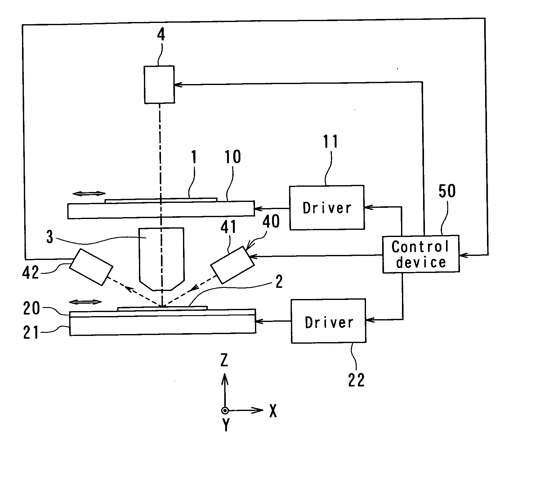
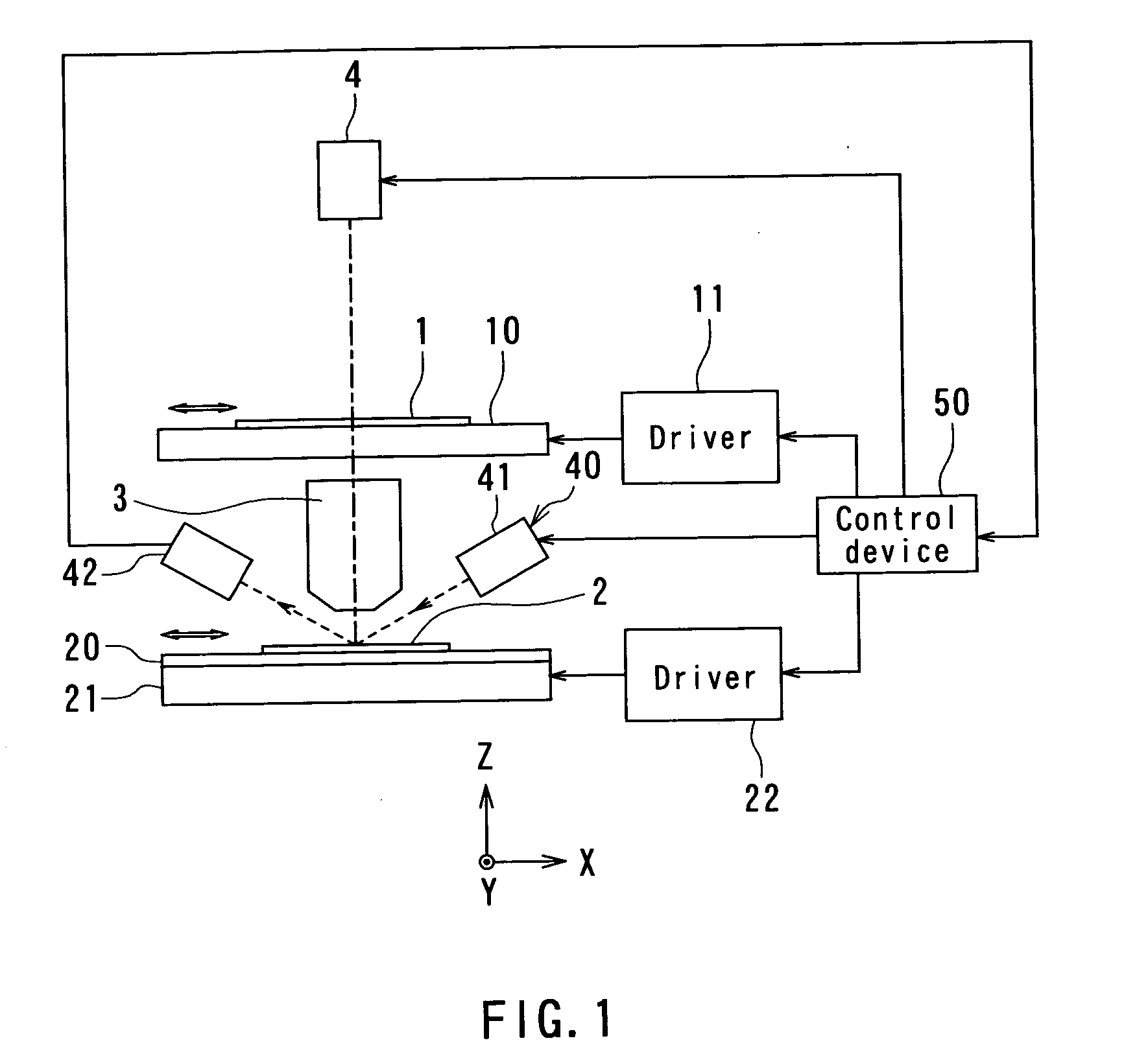
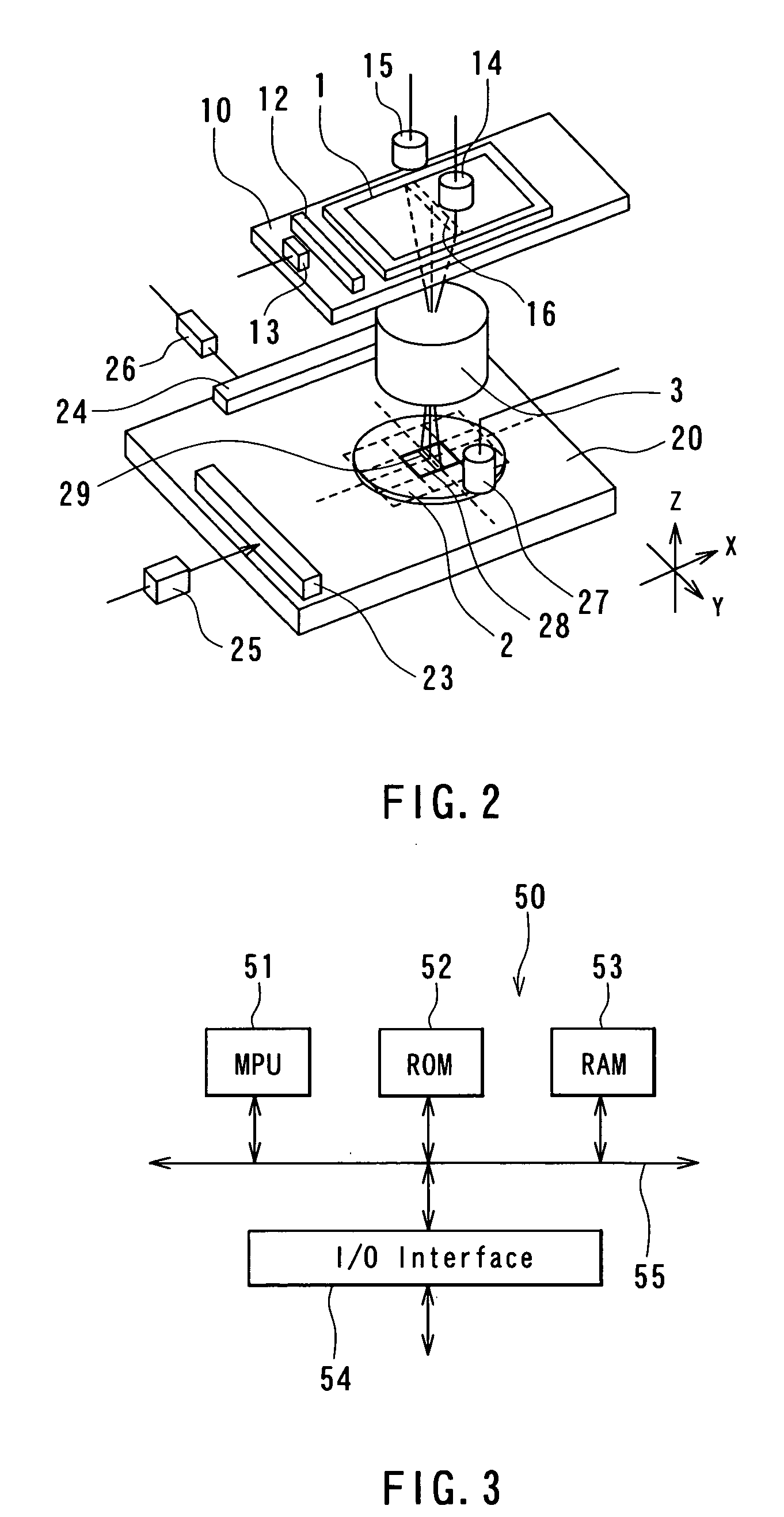
[0061] A preferred embodiment of the invention will now be described in detail with reference to the accompanying drawings. Reference is now made to FIG. 1 to FIG. 3 to describe the configuration of an exposure apparatus of an embodiment of the invention. FIG. 1 is a view for illustrating the main part of the exposure apparatus of the embodiment. FIG. 2 is a perspective view for illustrating the main part of the exposure apparatus. FIG. 3 is a block diagram showing the configuration of the control device of FIG. 1. The exposure apparatus of the embodiment is a step-and-scan exposure apparatus that is used in manufacturing microdevices by photolithography and used for exposing a substrate by projecting a pattern formed in a mask (hereinafter called a mask pattern) onto a plurality of regions on the substrate one by one by means of a scanning system.

[0062] As shown in FIG. 1 and FIG. 2, the exposure apparatus of the embodiment comprises: a mask stage 10 for retaining a mask 1; a subs...


PUM


Abstract

For each of pattern projection regions, a mask and a substrate are moved in synchronization with each other in an X direction while projecting a portion of a mask pattern through an optical projection system onto a portion of the pattern projection region. An exposure region is thereby shifted from one of two ends of the pattern projection region toward the other end, the two ends being opposed to each other in the X direction. If the pattern projection region is a peripheral projection region that has a portion located outside the edge of the substrate, of the two ends of the region opposed to each other in the X direction, the exposure region is shifted from the one end that is greater in length of a portion laid over the substrate toward the other end.

Description

BACKGROUND OF THE INVENTION [0001] 1. Field of the Invention [0002] The present invention relates to an exposure method and an exposure apparatus that are used in manufacturing microdevices through the use of photolithography and used for exposing a substrate by projecting a pattern formed in a mask (hereinafter called a mask pattern) onto a plurality of regions in the substrate one by one by means of a scanning system. [0003] 2. Description of the Related Art [0004] To manufacture microdevices by photolithography, a mask pattern is projected through an optical projection system onto a substrate on which a photoresist layer is formed, and the substrate is exposed by the light patterned by the mask pattern. A scanning exposure (lithography) apparatus and a step-and-scan exposure apparatus are known as exposure apparatuses used for such an exposure. [0005] The scanning exposure apparatus is operated such that a portion of the mask pattern is projected onto the substrate through the op...

Claims


Application Information

Patent Timeline
Patent Type & Authority Applications(United States)
IPC IPC(8): G03B27/42
CPCG03F7/70425
Inventor KAMIJIMA, AKIFUMIHATATE, HITOSHI
Owner TDK CORPARATION
Why Eureka
Try Eureka