
Doppler tracking optical monopulse

a technology of optical monopulse and doppler, which is applied in the direction of reradiation, distance measurement, instruments, etc., can solve the problems of limited velocity of guided munition having a hemispherical radome, and problems for the detector system used

Active Publication Date: 2006-02-23
LOCKHEED MARTIN CORP
View PDF9 Cites 20 Cited by
  • Summary
  • Abstract
  • Description
  • Claims
  • Application Information

AI Technical Summary

Benefits of technology

[0008] A first embodiment of the invention is an apparatus for determining the direction and speed of an object that reflects radiation relative to the apparatus. The apparatus comprises a laser source for emitting a laser beam and a beamsplitter for splitting this laser beam into two parts. The first part is a transmit beam that is subsequently directed toward the target, while the second part is a local oscillator beam. The transmit beam passes through a transmitting window system, while the portion of the transmit beam that is reflected by the target back to the apparatus, the Doppler shifted beam, passes through a receiving window system. The Doppler shifted beam has been Doppler shifted in frequency due to the radial speed of the target. The receiving window system, having Fresnel transmittance properties, defines an optical axis. The receiving window system is configured such that if the Doppler shifted beam is parallel to the optical axis, the Doppler shifted beam is incident upon a surface of the receiving window system at a boresight incidence angle. The boresight incidence angle is selected such that an instantaneous rate of change of the Fresnel transmittance as a function of angle of incidence at the boresight incidence angle is significantly different from zero. The Doppler shifted beam, having passed through the receiving window system, is combined with the local oscillator beam using four beam combiners. These combined Doppler shifted and local oscillator beams are incident upon four photomixers, which photomix the combined Doppler shifted and local oscillator beams. Each of the photomixers generates a respective photomixed signal. A portion of each photomixed signal is phase shifted by a corresponding phase shifting element, thereby generating corresponding shifted photomixed signals. Both the photomixed signals and the shifted photomixed signals are converted from analog signals to digital data using A / D converters. This digital data is then stored in a Doppler bin array. An angle processor subsequently determines the azimuth and elevation angles to the target relative to the window system optical axis using the digital data.

Problems solved by technology

While such laser guided munitions have been in operation for quite some time, the radome / detector design limits the velocity of these guided munitions.
The velocity of a guided munition having a hemispherical radome is limited due to the radome's aerodynamic drag.
However, this change in radome shape has created problems for the detector system used to guide the munition.
Moreover, the simple quadrant detectors used in a hemispherical radome are incompatible with the optical transmission properties of a more conic-shaped radome.
Further, while laser guided munitions exist, the requirement of using a continuous laser for illuminating the target is undesirable.
This creates additional guidance problems as the guided munition receives far less reflected laser signal, resulting in the need for more accurate guidance feedback based upon this limited reflected laser signal.
An additional drawback of many laser guided munitions is the requirement for an external designator.
This places the designator, for example the aircraft that released the guided munition, at risk.
Given the fact that the designator must be within laser range of the target, such laser guided munitions cannot be operated in a “fire and forget” mode that minimizes risk.
A still further issue with laser guided munitions is tracking a moving target.
This is especially true of certain countermeasures whose speed would not match that of a target, such as an aircraft.

Method used


Image

  • Doppler tracking optical monopulse
  • Doppler tracking optical monopulse
  • Doppler tracking optical monopulse

Examples


Embodiment Construction

[0025] Determining both the relative direction and speed of a target can be a complicated task. One proposed method for determining the relative direction of target is disclosed in related U.S. patent application Ser. No. 10 / 729,066, a previous invention of the present inventors. A brief summary of this related art follows as it also describes the direction detection portion of the present invention.

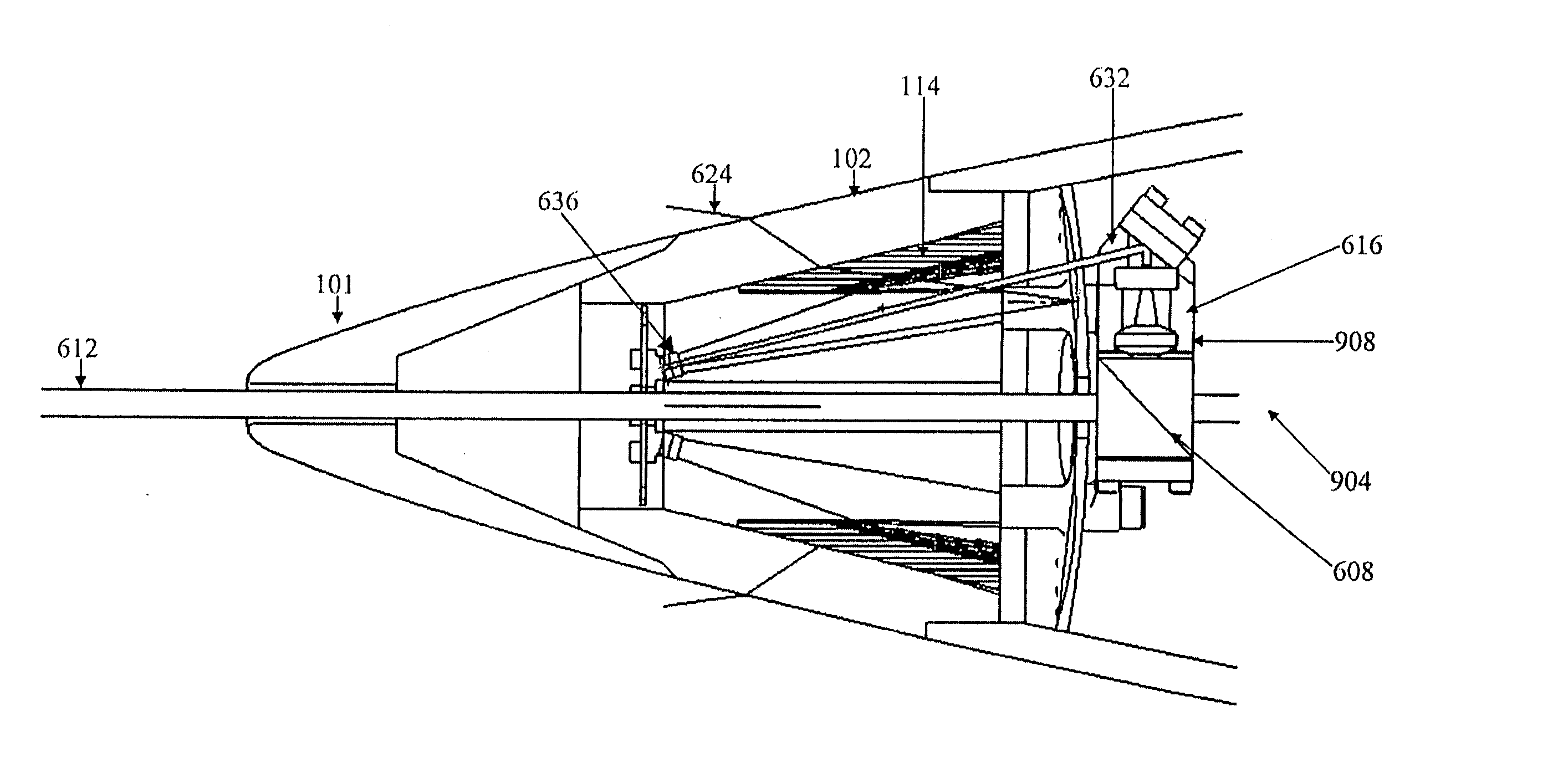
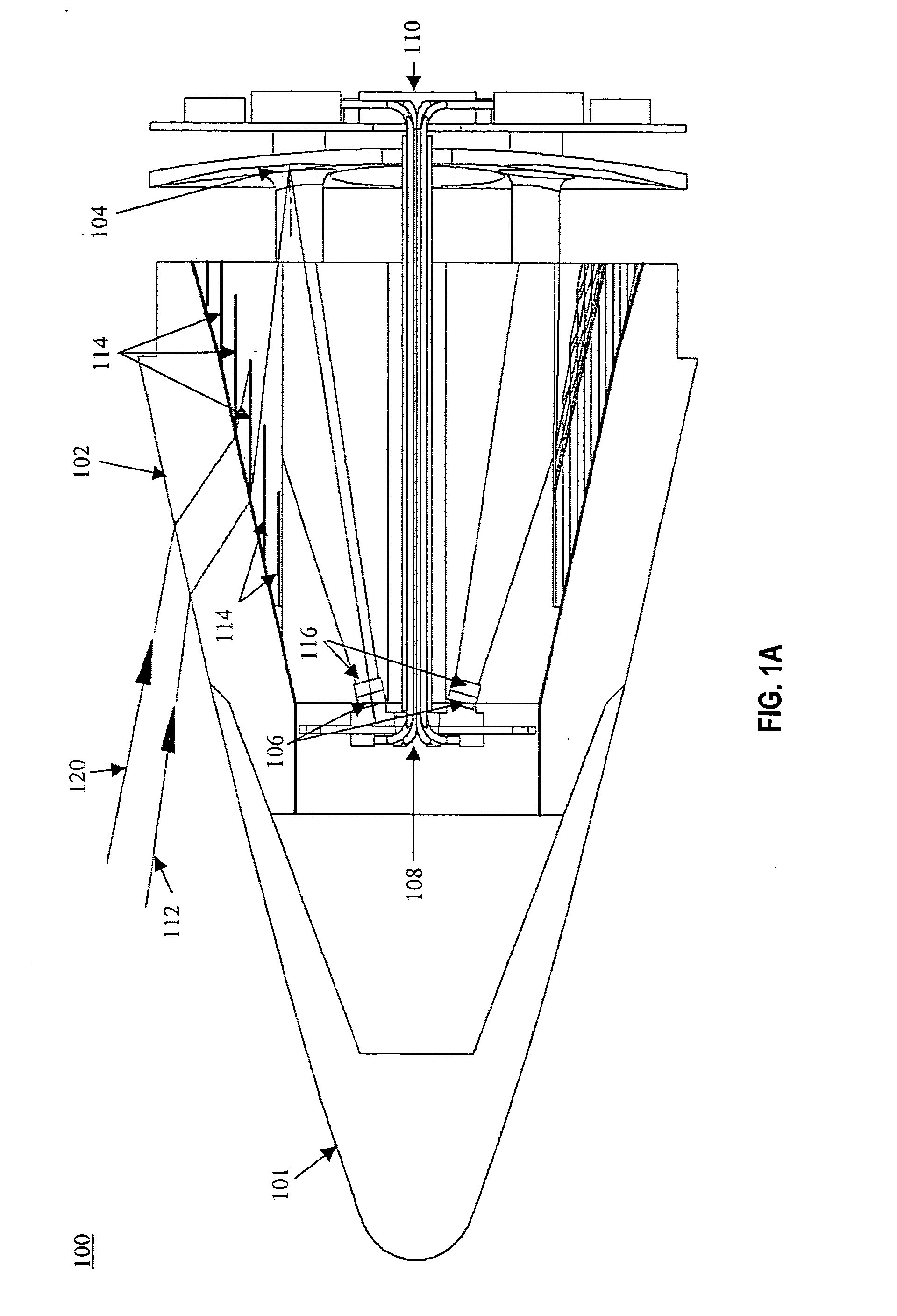
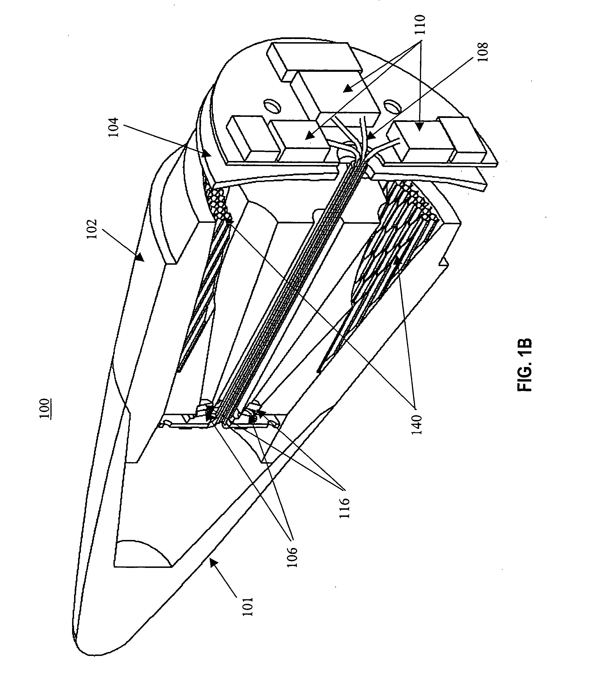
[0026]FIG. 1A illustrates a related art direction finding system 100 for use in a guided munition. The direction finding system 100 includes a radome 101 with a receiving window system 102 that receives and transmits therethrough a radiation pulse 112, typically a laser pulse. The receiving window system 102 must be made of a material that transmits the radiation pulse 112, but can also withstand aerodynamic heating due to the velocity of the guided munition. Moreover, the receiving window system 102 must be able to withstand abrasion, such as that caused by dust or sand impacting the r...


PUM


Abstract

A method and apparatus for finding a relative direction to, a radial speed of, and a distance to a target is described. A laser source illuminates the target and the Doppler shifted return beam is incident upon a window system at an angle and is transmitted therethrough. The magnitude of the transmitted Doppler shifted beam decreases due to Fresnel transmittance. Opposing photomixers then detect this transmitted Doppler shifted beam, thereby creating a pair of detection signals that are mixed with a local oscillator signal. The mixing process creates Doppler frequency signals that are subsequently processed to determine the radial speed of the target. Due to the Doppler frequency component of the signals, objects in the same direction, but moving at different radial speeds, can be discriminated, as the relative direction processing occurs after the Doppler processing.

Description

FIELD OF THE INVENTION [0001] The present invention relates to a method of and apparatus for detecting radiation. In particular, the present invention provides for determining the relative direction and speed of an object that reflects radiation, for example, for munition guidance purposes. BACKGROUND OF THE INVENTION [0002] Advances in technology have led to improvements in the precision of guided munitions. However, as guidance systems have become more sophisticated, the need for even greater precision is apparent. As military targets are frequently found in civilian surroundings, highly precise guidance systems are required to destroy these military targets while minimizing collateral damage to the civilian surroundings. One approach to increasing the precision of guided munitions is through using a laser designator to illuminate the desired target. A quadrant detector within the radome of the guided munition then guides the munition to maximize the reflected laser signal receive...

Claims


Application Information

Patent Timeline
Patent Type & Authority Applications(United States)
IPC IPC(8): G01C3/08G01P3/36
CPCF41G7/226G01S17/50G01S3/784F41G7/2293
Inventor WILLIAMS, BRETT A.TURNER, MARK A.BAKER, BRIAN C.
Owner LOCKHEED MARTIN CORP
Learn More