
Storing apparatus

a technology for storing equipment and storage devices, which is applied in the field of storage equipment, can solve the problems of difficult replacement of a built-in hard disk with a new one, difficult to secure the free capacity, and lack of versatility of storage equipment, and achieve the effect of enhancing convenien

Inactive Publication Date: 2006-02-23
HITACHI LTD
View PDF0 Cites 38 Cited by
  • Summary
  • Abstract
  • Description
  • Claims
  • Application Information

AI Technical Summary

Benefits of technology

[0011] It is an object of the present invention to provide a storing apparatus having enhanced convenience.
[0013] In accordance with the present invention, it is possible to provide a storing apparatus having enhanced convenience.

Problems solved by technology

In this case, however, since the file deletion is performed by a method uniformly selected and set by a user from many methods, the storage apparatus lacks versatility.
However, it is difficult to replace a hard disk built in the apparatus with another hard disk, for example, a large capacity hard disk.
However, in a case in which there is no method of securing the necessary free capacity of the hard disk, except for the deletion of files, it is difficult to secure the free capacity, without causing the user to experience a feeling of resistance against the deletion of the stored programs.
However, in securing the free capacity by recompression, the securable free capacity is limited.
However, according to Patent Document 3, since it is assumed that the captured image is reproduced in the external image processing device, which serves as a destination in the transfer, the captured image, once it has been transferred, cannot be displayed in the imaging device.
However, an increase in the capacity of the hard disk is not a basic solution.
Further, it is difficult to secure the free capacity, without causing the user to experience a feeling of resistance against the deletion of the stored programs.
However, since all of the above-described Patent Documents have given no consideration to how data should be deleted according to any priority, the consideration of priority is problematic.

Method used


Image

  • Storing apparatus
  • Storing apparatus
  • Storing apparatus

Examples


first embodiment

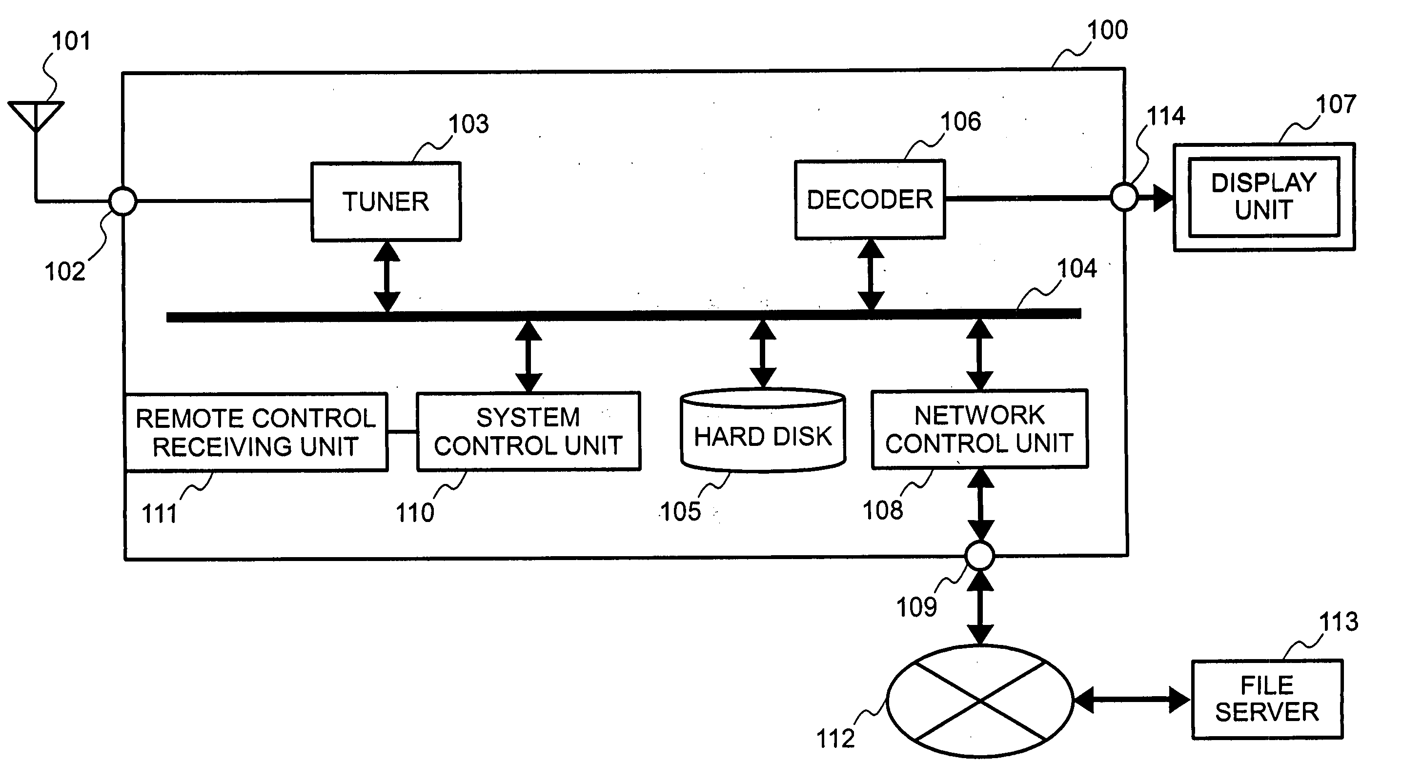
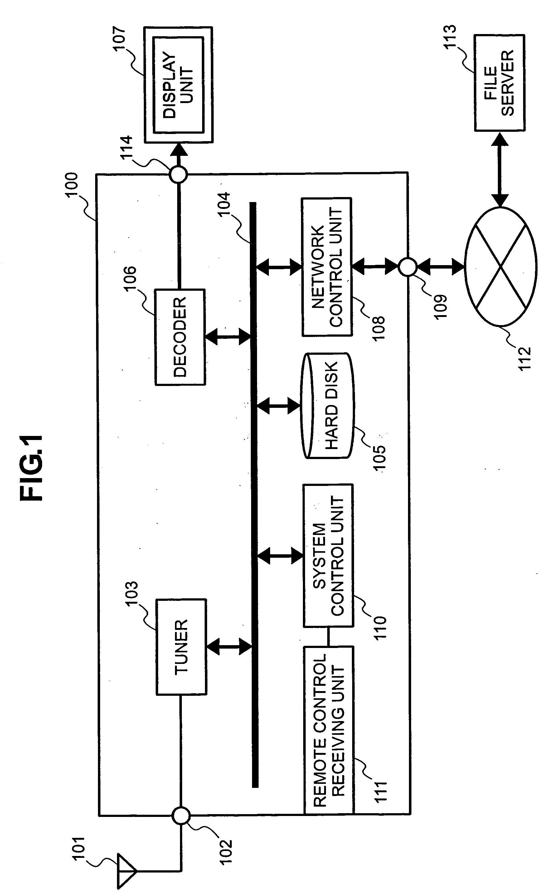
[0023]FIG. 1 shows a first embodiment of the present invention.

[0024] A storing apparatus 100 includes an antenna input terminal 102, a tuner 103, a data bus 104, a hard disk 105, a decoder 106, a network control unit 108, a network terminal 109, a system control unit 110, a remote control receiving unit 111, and a display unit connection terminal 114. An antenna 101 is connected to the antenna input terminal 102; a display unit 107 is connected to the display unit connection terminal 114; and a network 112 is connected to the network terminal 109.

[0025] First, an operation that is performed when recording a program will be described below.

[0026] A user sets a timer using a remote control device (not shown) or the like. Timer reservation information from the remote control device is transferred by an infrared ray and is demodulated by the remote control receiving unit 111. Then, the demodulated information is inputted to the system control unit 110. The system control unit 110 pe...


PUM

PropertyMeasurementUnit
compression ratioaaaaaaaaaa

Abstract

In a storing apparatus having a built-in recording medium, which stores program files, if there is no method of securing a free capacity of the recording medium, except for deletion of files, a user may have a feeling of resistance against the deletion of stored program files. Further, in securing the free capacity through recompression, there is a limitation to achieving a securable capacity. These problems can be solved by increasing the capacity of the disk to some extent, but this method is insufficient. Thus, a storing apparatus is provided in which, when the capacity of the recording medium is small, selected program stream stored in a hard disk is outputted via a network control unit to an external storage medium, and, after that program stream is outputted, the corresponding program stream is deleted from the hard disk.

Description

BACKGROUND OF THE INVENTION [0001] The present invention relates to a storing apparatus for storing broadcast programs. [0002] Japanese Patent Laid-Open No. 2003-289490 (hereinafter referred to as Patent Document 1) discloses a storage apparatus which secures a required storage capacity by automatically deleting files, such that a recording medium provided therein can be effectively used and a failure in storing information due to an insufficient capacity can be prevented. In this case, however, since the file deletion is performed by a method uniformly selected and set by a user from many methods, the storage apparatus lacks versatility. In order to solve this problem, in Patent Document 1 discloses a technique in which a broadcast program is stored in a hard disk drive (HDD) 6 or the like, together with data regarding a storage retention condition. Specifically, stored data regarding the storage retention condition is checked by a microprocessor unit (MPU) 7, and selected broadcas...

Claims


Application Information

Patent Timeline
Patent Type & Authority Applications(United States)
IPC IPC(8): G11B19/02G11B5/09
CPCG11B20/00007H04N9/8042G11B20/10G11B27/034G11B27/105G11B27/34G11B27/36G11B2220/2516G11B2220/2562G11B2220/455H04N5/76H04N5/765H04N5/781H04N5/85G11B20/0021
Inventor NAKAMURA, TAKUSUGIMURA, NAOZUMI
Owner HITACHI LTD
Learn More