Chemical analysis apparatus

a technology of chemical analysis and apparatus, which is applied in the direction of positive displacement liquid engines, laboratory glassware, instruments, etc., can solve the problems of lowering the dispensing accuracy, difficult to handle wide-ranging liquid volumes for analysis, and difficulty in dispensing, etc., and achieves high accuracy and high mixing accuracy.

Inactive Publication Date: 2006-02-23
HITACHI HIGH-TECH CORP
View PDF6 Cites 251 Cited by
  • Summary
  • Abstract
  • Description
  • Claims
  • Application Information

AI Technical Summary

Benefits of technology

[0009] In view of the above problems, an object of the present invention is to provide a chemical analysis apparatus whereby liquids for analysis varying in volumes can be analyze...

Problems solved by technology

The following problems exist concerning the application of the technology disclosed in the specification of U.S. Pat. No. 6,565,727 to a chemical analysis apparatus for analyzing small quantities of substances contained in vivo.
First, the range of small volumes of liquids (liquids for analysis such as samples and reagents) is determined based on the gap between 2 plate members and electrode size at the time of c...

Method used


Image

  • Chemical analysis apparatus
  • Chemical analysis apparatus
  • Chemical analysis apparatus

Examples


Embodiment Construction

[0021] Embodiments of the present invention will be described below based on figures.

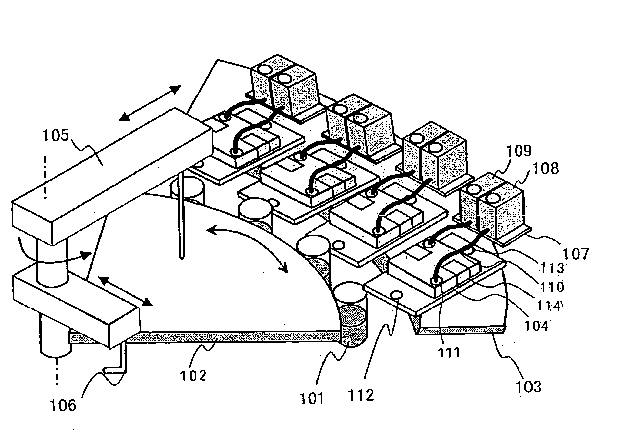
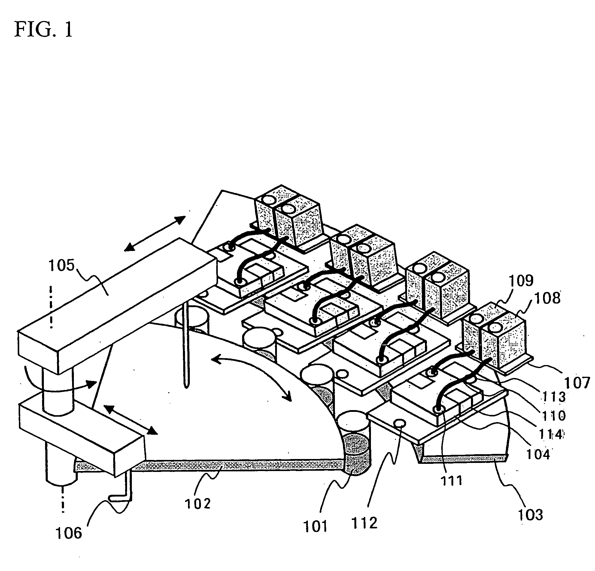
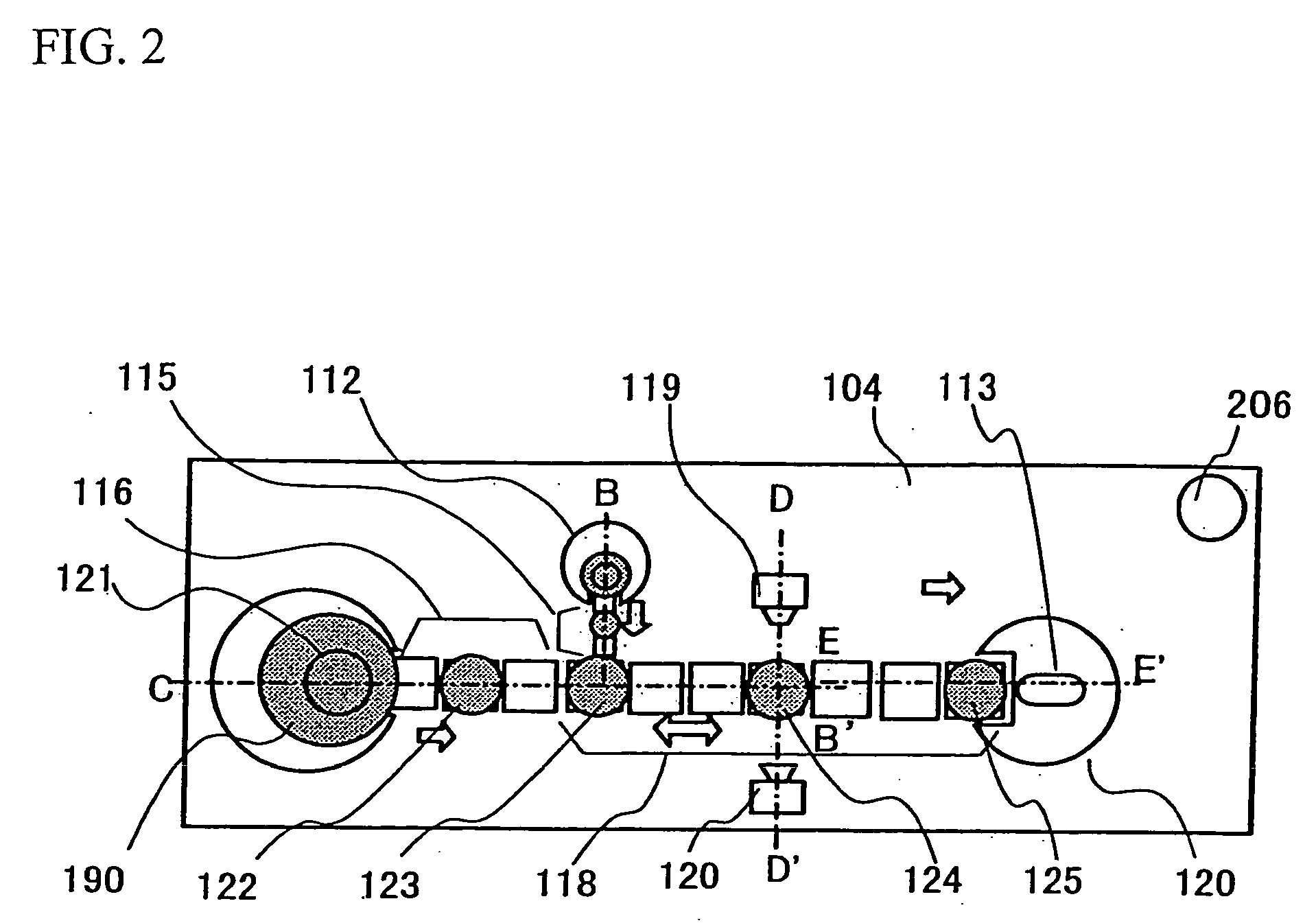
[0022] Embodiments are described using FIGS. 1 to 7. FIG. 1 is a schematic perspective view of the entire system. FIG. 2 shows a top view of substrates for analysis. FIG. 3 is a sample-dispensing section and shows a sectional view taken along the line B-B′ in FIG. 2. FIG. 4 is a reagent-dispensing section and shows a sectional view taken along the line C-B′ in FIG. 2. FIG. 5 is a detection section and shows a sectional view taken along the line D-D′ in FIG. 2. FIG. 6 is a waste fluid section and shows a sectional view taken along the line E-E′ in FIG. 2.

[0023] The chemical analysis apparatus is composed of, as shown in FIG. 1, sample cups 101 containing biological samples such as sera, a sample disc 102 that rotationally moves the sample cups 101, substrates for analysis 104 for analyzing samples placed on an analysis disc103, a sample-dispensing probe 105 for dispensing samples from the sample cu...


PUM


Abstract

A chemical analysis apparatus is equipped with analysis sections having openings, means for supplying samples or reagents from the openings, means for combining and mixing samples with reagents to obtain droplets as liquids to be measured, and means for measuring the physical properties of the liquids to be measured during reaction or after completion of reaction. Furthermore, plate members are provided facing each other in analysis sections and a plurality of electrodes are provided on the plate member faces that face each other. Voltage is applied from the plurality of electrodes to the droplets of the samples and the reagents.

Description

[0001] The present application claims priority from Japanese application JP2004-237479 filed on Aug. 17, 2004, the content of which is hereby incorporated by reference into this application. BACKGROUND OF THE INVENTION [0002] The present invention relates to a chemical analysis apparatus appropriate for analyzing small quantities of substances contained in vivo. [0003] The specification of U.S. Pat. No. 6,565,727 discloses a method by which: a plate member having rows of a plurality of electrodes that are insulated from each other is provided facing a single common electrode plate; and droplets of small volume in a filling liquid that fills the gap between 2 plates are transported along the electrode rows by consecutively applying voltage to the electrode rows so as to generate attraction between the electrode faces and droplets. [0004] The following problems exist concerning the application of the technology disclosed in the specification of U.S. Pat. No. 6,565,727 to a chemical an...

Claims


Application Information

Patent Timeline
IPC IPC(8): G01N35/00
CPCB01F11/0071G01N2035/102B01F13/0076B01L3/502746B01L3/502784B01L2200/0605B01L2300/0654B01L2300/0867B01L2300/089B01L2400/0427F04B19/006G01N35/1016G01N2035/00158G01N2035/00237B01F13/0071B01F31/65B01F33/3021B01F33/3031
Inventor YAMAKAWA, HIRONOBUENOKI, HIDEOHARADA, KUNIOADACHI, SAKUICHIROMIMURA, TOMONORI
Owner HITACHI HIGH-TECH CORP
Why Eureka
Try Eureka