Discharge-enhanced atmospheric pressure chemical vapor deposition

a technology of atmospheric pressure and chemical vapor deposition, which is applied in the direction of chemical vapor deposition coating, coating, plasma technique, etc., can solve the problems of preventing the use of cvd for surface modification or deposition, vacuum chambers and pumping systems greatly increase the cost and difficulty in scaling up for large volume manufacturing and continuous processes, and the cost of noble gases is higher. , to achieve the effect of increasing the overall process cost, the effect of reducing the cost of production

Inactive Publication Date: 2006-02-23
ARKEMA INC
View PDF17 Cites 32 Cited by
  • Summary
  • Abstract
  • Description
  • Claims
  • Application Information

AI Technical Summary

Benefits of technology

[0033] In conventional low pressure plasma enhanced CVD, the deposition kinetics are also enhanced by electrical means, but the key advantage of the present invention over low pressure plasma enhanced CVD is that the electrical discharge nozzle design can easily be expanded to coat arbitrarily wide substrates such as but not limited to sheets. The method does not require vacuum chambers or vacuum pumps, which are expensive and / or difficult to scale up for coating large substrates. The exhaust system only requires standard blowers, so the entire process occurs essentially at atmospheric pressure. Another advantage is that the equipment is mounted above the substrate, and no part is in contact with the substrate. The substrate does not need to be fed into a coating chamber or electrode assembly which surrounds the substrate on top and bottom. This is an advantage where the coating equipment must be installed without disturbing the existing process line, or where it is impractical to manipulate or surround the substrate (e.g. continuous glass or polymer sheet processes).
over low pressure plasma enhanced CVD is that the electrical discharge nozzle design can easily be expanded to coat arbitrarily wide substrates such as but not limited to sheets. The method does not require vacuum chambers or vacuum pumps, which are expensive and / or difficult to scale up for coating large substrates. The exhaust system only requires standard blowers, so the entire process occurs essentially at atmospheric pressure. Another advantage is that the equipment is mounted above the substrate, and no part is in contact with the substrate. The substrate does not need to be fed into a coating chamber or electrode assembly which surrounds the substrate on top and bottom. This is an advantage where the coating equipment must be installed without disturbing the existing process line, or where it is impractical to manipulate or surround the substrate (e.g. continuous glass or polymer sheet processes).

Problems solved by technology

These high temperatures prevent the use of CVD for surface modification or deposition on thermally sensitive substrates such as polymers.
The use of vacuum chambers and pumping systems greatly increases the cost and difficulty in scale-up for large volume manufacturing and continuous processes.
However, the principal disadvantage oftechniques which use noble gases is that the higher cost of noble gases increases the overall process costs.
The use of noble gases is a particular disadvantage in atmospheric pressure techniques compared to low pressure PECVD because much higher volumes of gases are required.
However, the placement of the substrate between the electrodes suffers from several disadvantages including increased difficulty of substrate manipulation during manufacturing, potential interference of the discharge by the substrate, and potential increased damage to the substrate surface created by the discharge.
Like the other references cited above, WO 00 / 70117 does not address the high cost of vacuum processing or noble gases, either of which makes conventional discharge deposition methods of the type disclosed in WO 00 / 70117 impractical for many coating applications.
However, each of these teach the use of noble gases such as He, Ne, or Ar to stabilize the plasma without addressing the increased processing costs.
This configuration is disadvantageous in that the coating area is highly limited with a single device.
Scale-up for coating large areas using a single or multiple devices is difficult, both in terms of manufacture and maintaining a uniform discharge across the surface.
Similarly, U.S. Patent Application Publication Nos. 2002 / 0171367 A1 and 2003 / 0129107 A1 do not specifically require noble gases, but also use cylindrical electrode configuration either as a single device or an array, making scale-up to coat or modify large surface areas difficult.

Method used


Image

  • Discharge-enhanced atmospheric pressure chemical vapor deposition
  • Discharge-enhanced atmospheric pressure chemical vapor deposition
  • Discharge-enhanced atmospheric pressure chemical vapor deposition

Examples


example 1

SnO2 Deposition at Room Temperature (25° C.) by DECVD

DECVD System Description

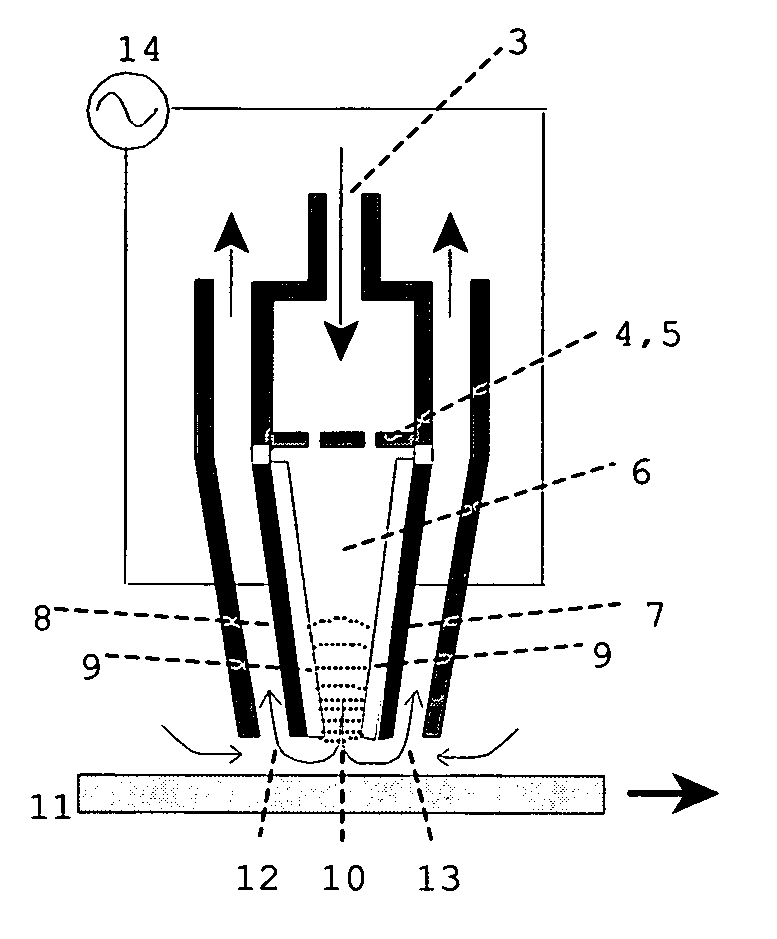
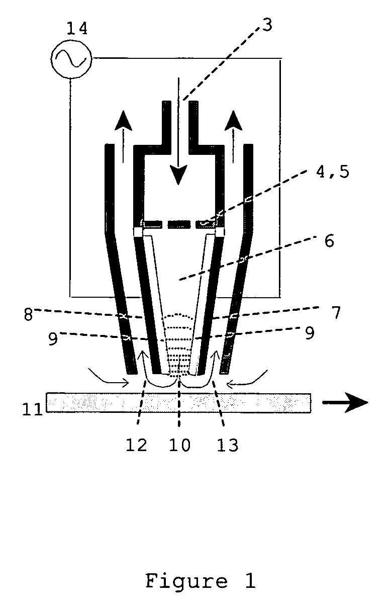
[0057] The DECVD reactor used during SnO2 deposition is depicted in FIG. 4a. The reactor body was made out of nonconductive machinable alumina silicate ceramic with a dielectric strength of 100 V / mil (0.5 inch thick walls). The reactor shown in FIG. 4 was equipped with two side gas entrance slots, such as two side slots 1 and 2, and a central slot 3. Slots 1 and 2 were rectangular 0.5×7 inches. The central slot was circular 0.5 inch in diameter. To allow for adequate homogeneous distribution of gas coming from slot #3 a showerhead, #5 was introduced in the reaction stream, as shown in FIG. 4. The High voltage (HV) electrode, #4, 4 inches wide and 7 inch long was tightly fitted between ceramic walls of the ceramic reactor parallel to the substrate.

[0058] The electrode comprised of ⅛ inch in diameter 6-inch long brass rods encapsulated in Al2O3 ceramic roads as shown in FIG. 4b. When the brass electrode, ...


PUM

PropertyMeasurementUnit
temperatureaaaaaaaaaa
surface temperatureaaaaaaaaaa
temperaturesaaaaaaaaaa

Abstract

A discharge-enhanced CVD apparatus and method utilizes a nozzle containing electrodes to generate a high voltage electrical discharge at or near atmospheric pressure in the absence of a stabilizing or arc-suppressing noble gas. Reactants are passed directly through or / and under the discharge before being directed to the surface of a substrate to be coated.

Description

BACKGROUND OF THE INVENTION [0001] 1. Field of the Invention [0002] This invention relates to a method and apparatus for performing chemical vapor deposition (CVD) at atmospheric pressure, and preferably at relatively low substrate temperatures, by passing the reactants through an electrical discharge such as a dielectric barrier, glow or corona arc discharges in order to raise the reactivity of the reactants and thereby increase the rate of surface reactions that result in coating or surface modification of the substrate. [0003] The invention also relates to a CVD coating nozzle that incorporates electrodes to produce an electrical discharge. [0004] 2. Description of Related Art [0005] Chemical vapor deposition is a well-known process by which gas phase reactants are directed to a heated substrate, where surface reactions can cause a modification to the surface of the substrate or a thin layer of material to be deposited on the substrate. This method has been used to modify various...

Claims


Application Information

Patent Timeline
Patent Type & Authority Applications(United States)
IPC IPC(8): H05H1/24C23C16/00
CPCC23C16/407H05H1/24C23C16/545C23C16/50H05H1/2406H05H1/42H05H2240/10H05H2245/40
Inventor CULP, THOMASKOROTKOV, ROMANGUPTA, RAVI
Owner ARKEMA INC
Why Eureka
Try Eureka