
Physiological sensor device

a sensor device and sensor technology, applied in the field of physiological sensor devices, can solve the problems of straps interacting with women's bras or other undergarments, uncomfortable straps to the extent that they constrict users' chests, and not being desirable, so as to improve the comfort of users wearing heart rate monitors and improve the comfort level

Inactive Publication Date: 2006-02-23
CARDIO TECH
View PDF19 Cites 69 Cited by
  • Summary
  • Abstract
  • Description
  • Claims
  • Application Information

AI Technical Summary

Benefits of technology

[0007] In view of the foregoing, a broad objective of the present invention is to provide an improved heart rate monitoring device for individuals to use in monitoring their exercise level. Another objective of the present invention is to improve the comfort of users wearing heart rate monitors. Another objective is to provide reliable heart rate data while maintaining this improved level of comfort.

Problems solved by technology

Nevertheless, manufacturers of heart rate monitors believe that a certain segment of the exercising population has refrained from using heart rate monitors because of discomfort or other issues caused by the sensor strap being worn at the chest location.
This discomfort includes problems for some wearers relating to a tendency of the strap to slip down off of their chest toward their lower chest and waist regions.
For female users, there is the issue of the strap interacting with the women's bra or other undergarments.
In addition, for certain exercisers that are breathing heavily, the strap may be uncomfortable to the extent it constricts the user's chest.
Further, to properly position or remove the chest strap, a user may find it necessary to remove their shirt, which may not be desirable in certain situations.

Method used


Image

  • Physiological sensor device
  • Physiological sensor device
  • Physiological sensor device

Examples


Embodiment Construction

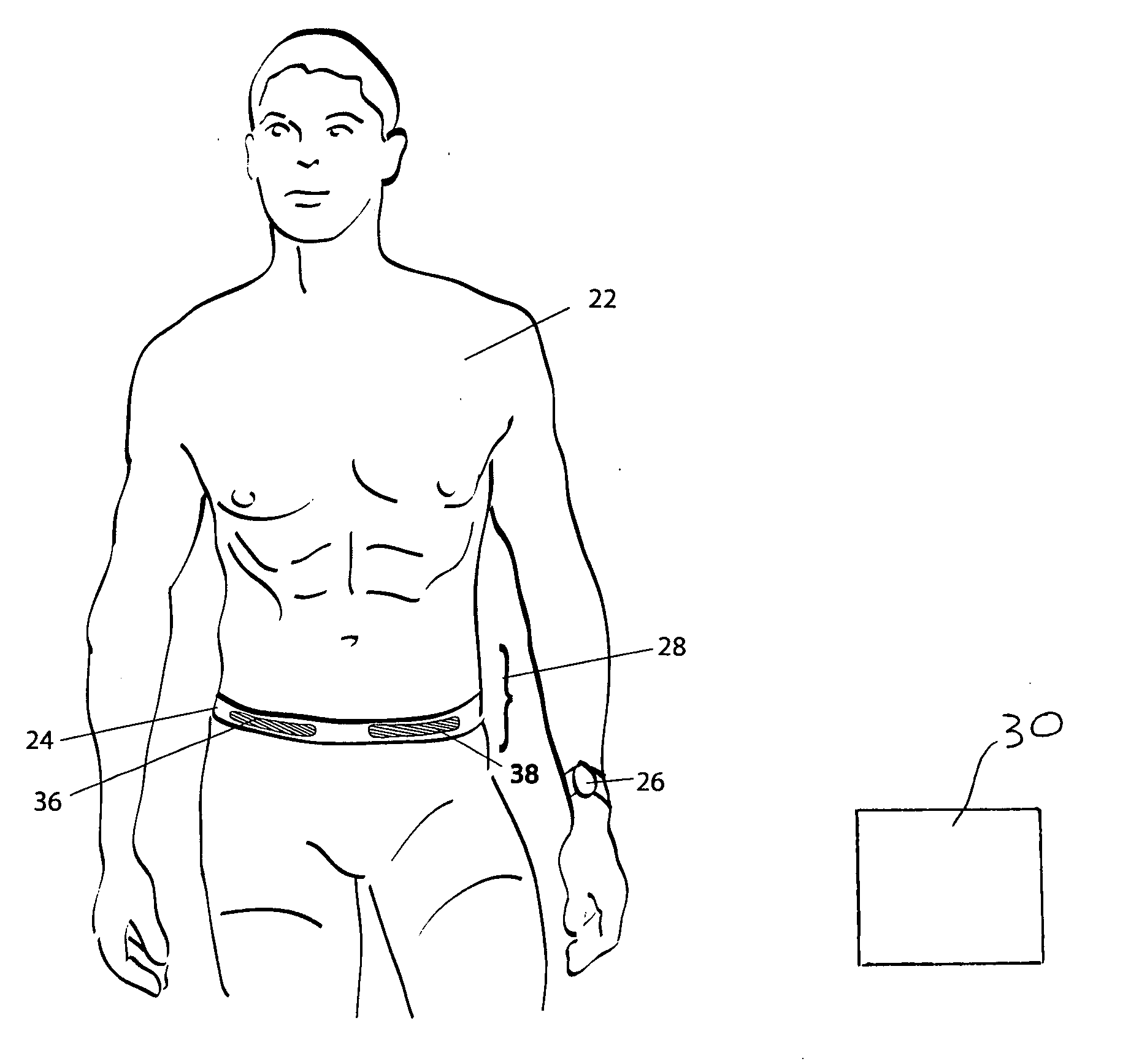
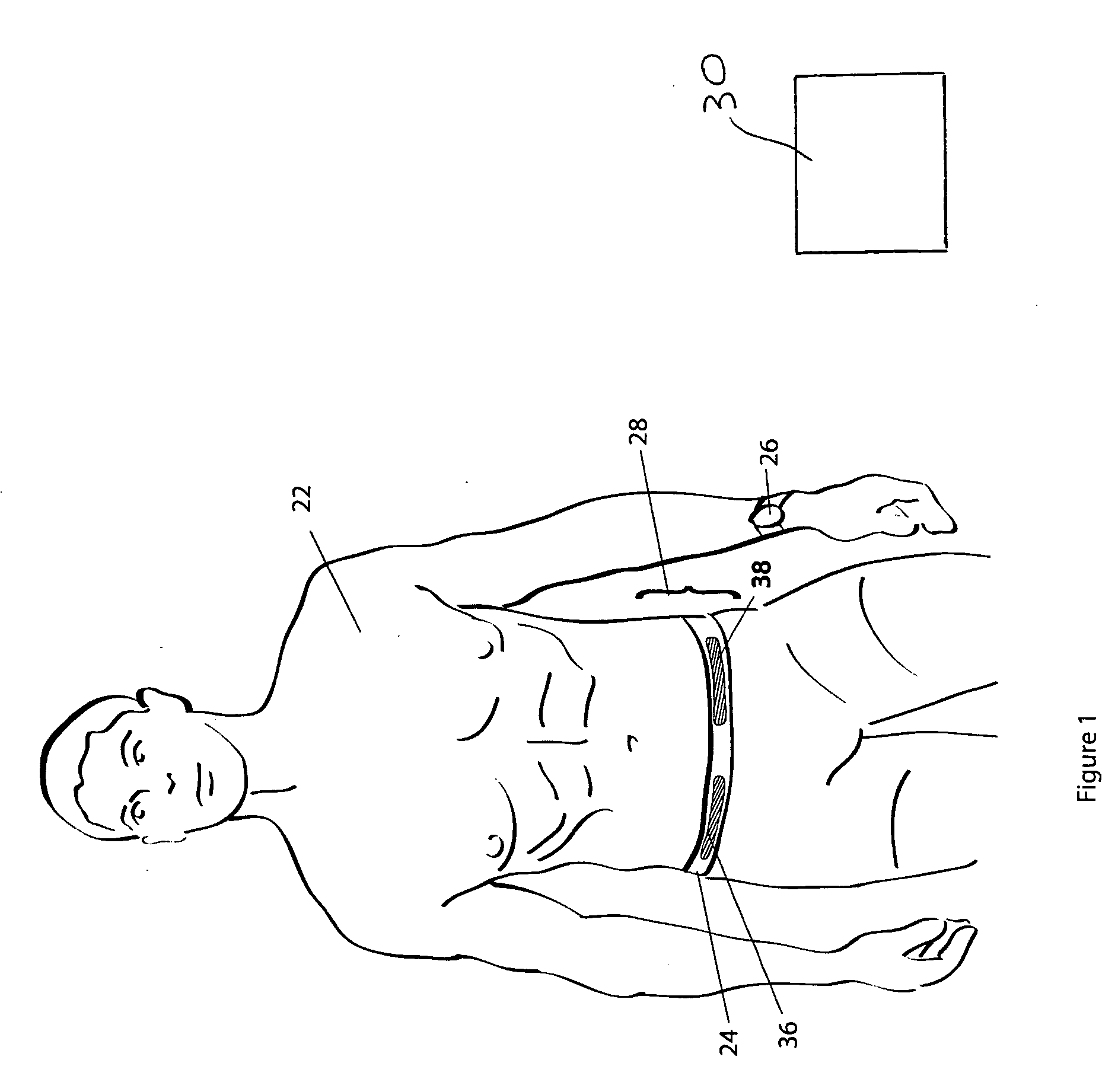
[0022] Reference will now be made to the accompanying drawings, which assist in illustrating the various pertinent features of the present invention. Although the present invention will now be described primarily in conjunction with a heart rate monitor having a plurality of sensors on a belt, it should be expressly understood that the present invention may be applicable to other applications where it is required / desired to measure electrical signals on the skin of a wearer. In this regard, the following description of a heart rate monitor is presented for purposes of illustration and description. Furthermore, the description is not intended to limit the invention to the form disclosed herein. Consequently, variations and modifications commensurate with the following teachings, and skill and knowledge of the relevant art, are within the scope of the present invention. The embodiments described herein are further intended to explain modes known of practicing the invention and to enab...


PUM


Abstract

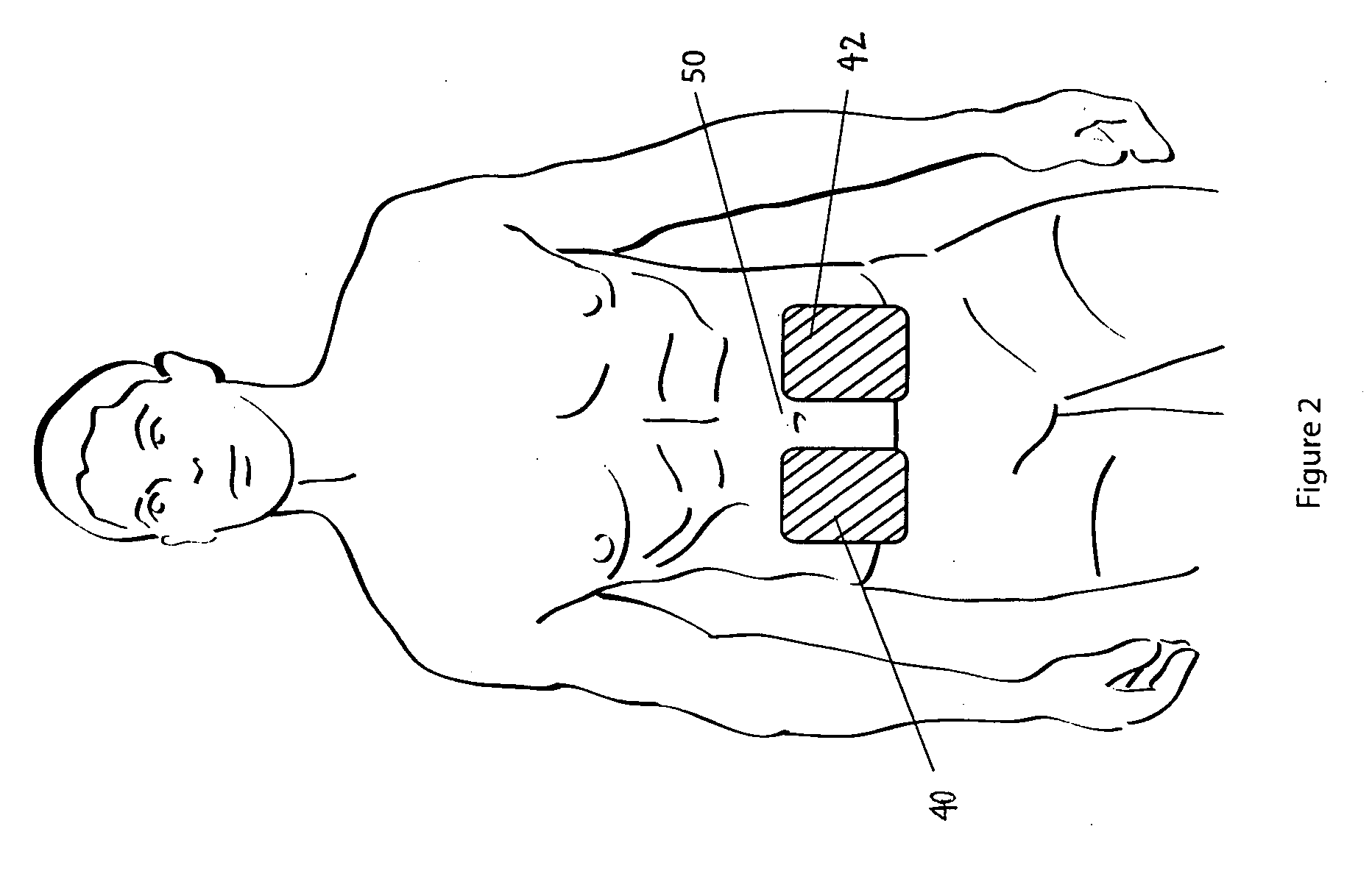
A heart rate monitoring system for use in sport and fitness training that includes a sensor belt worn on the waist of the user and a display device worn on the wrist of the user. The sensor belt has a pair of sensors that can be located on opposite sides of the body in various locations, such as near the kidneys, near the ilium bones in the pelvis, or on the front abdominal area of the user. Various signal processing techniques are employed to extract the degraded signal that is available at the waist area as compared to the chest area. These signal-processing techniques include bandpass filtering, an adaptive time window, a delayed transmission to allow for correction methods such as missed beat replacement and extra beat deletion, a lead off detection and adjustment algorithm, automatically adjustable gain control, and waveform detection and characterization.

Description

[0001] The present invention relates generally to a sensor device for measuring heart rate during exercise and displaying this information for the user, and more particularly to an improvement relating to the position of the sensor and to algorithms related thereto. BACKGROUND OF THE INVENTION [0002] Equipment for measuring electrical signals associated with the human heart were first developed over 110 years ago. This branch of science, known as electrocardiography, is used to produce a representation of the electrical signals in the heart known as an electrocardiogram (often abbreviated as EKG or ECG). Today, an ECG commonly involves the use of twelve to fifteen electrodes placed at various locations on the body. ECGs are used for a variety of purposes, but generally they are all diagnostic in nature. That is, ECGs are commonly used to diagnose diseases related to the heart. Because of the great importance of this issue and because of the number of electrodes used and the requirem...

Claims


Application Information

Patent Timeline
IPC IPC(8): A61B5/02
CPCA61B5/02438
Inventor DOTTER, JAMES E.FARRELL, DAVID J.GILBERT, JAMES A.
Owner CARDIO TECH
Learn More