Electrical heat and vibrating device

a technology which is applied in the field of electric heat and vibrating device, can solve the problems of lack of portability, lack of self-administration, lack of key features of self-administration by the patient, etc., and achieve the effect of high effectiveness

Inactive Publication Date: 2006-02-23
GROSS JULIA
View PDF12 Cites 6 Cited by
  • Summary
  • Abstract
  • Description
  • Claims
  • Application Information

AI Technical Summary

Benefits of technology

[0008] The present invention incorporates several prior arts into a highly effective device that gives temporary relief to people suffering from inflammation of the joints thru heat and vibration therapy.
[0009] More particularly, this device is designed to be lightweight, portable, completely self-contained low voltage, and self-administered therapeutic apparatus. By utilizing a thermodynamic gloving system to retain heat, the device only needs to raise the temperature of the hand slightly above regular body temperature in order to be effective. This allows for true portability and easy self-administration by the patient.
[0010] The inner glove acts as a heat sink. It provides rapid heat transference by utilizing materials that have a low resistance to heat such as silk, nylons, etc. The external glove acts as a heat resistor. It provides resistance to heat flow from the heating element attached to the inner glove. The exterior glove is made from material that has low thermal conductivity and / or has thermal insulation attached to it in order to increase the thermal resistance to heat flow—ex. Leather with a thick polyester backing.
[0014] The therapeutic system can be strapped to the wearer's hand with a VELCO type of strap or the glove can fit the wearer's hand snuggly and achieve the desired effects from the operation of the vibrator and heater.

Problems solved by technology

Lack of portability and lack of self-administration were key problems past mechanical devices.
French patent 645,147 provided temporary relief by increasing blood flow through heat and massage therapy but it lacked key features of self-administration by the patient and portability.
U.S. Pat. Nos. 5,601,529, 1,498,680, and 5,577,273 offers temporary relief for aching muscles but fails to offer self-administration.
Further, these devices fail to increase blood flow.
U.S. Pat. No. 4,979, 502 offers temporary relief for aching muscles but fails to deliver to maximum relief to body joints.
It fails to trap maximum heat at the joints.
Further, this device is heavy due to the large size batteries that are needed with the glove item.
Further, the system would not be self-contained because batteries would have to be carried on the belt.

Method used


Image

  • Electrical heat and vibrating device
  • Electrical heat and vibrating device
  • Electrical heat and vibrating device

Examples


Embodiment Construction

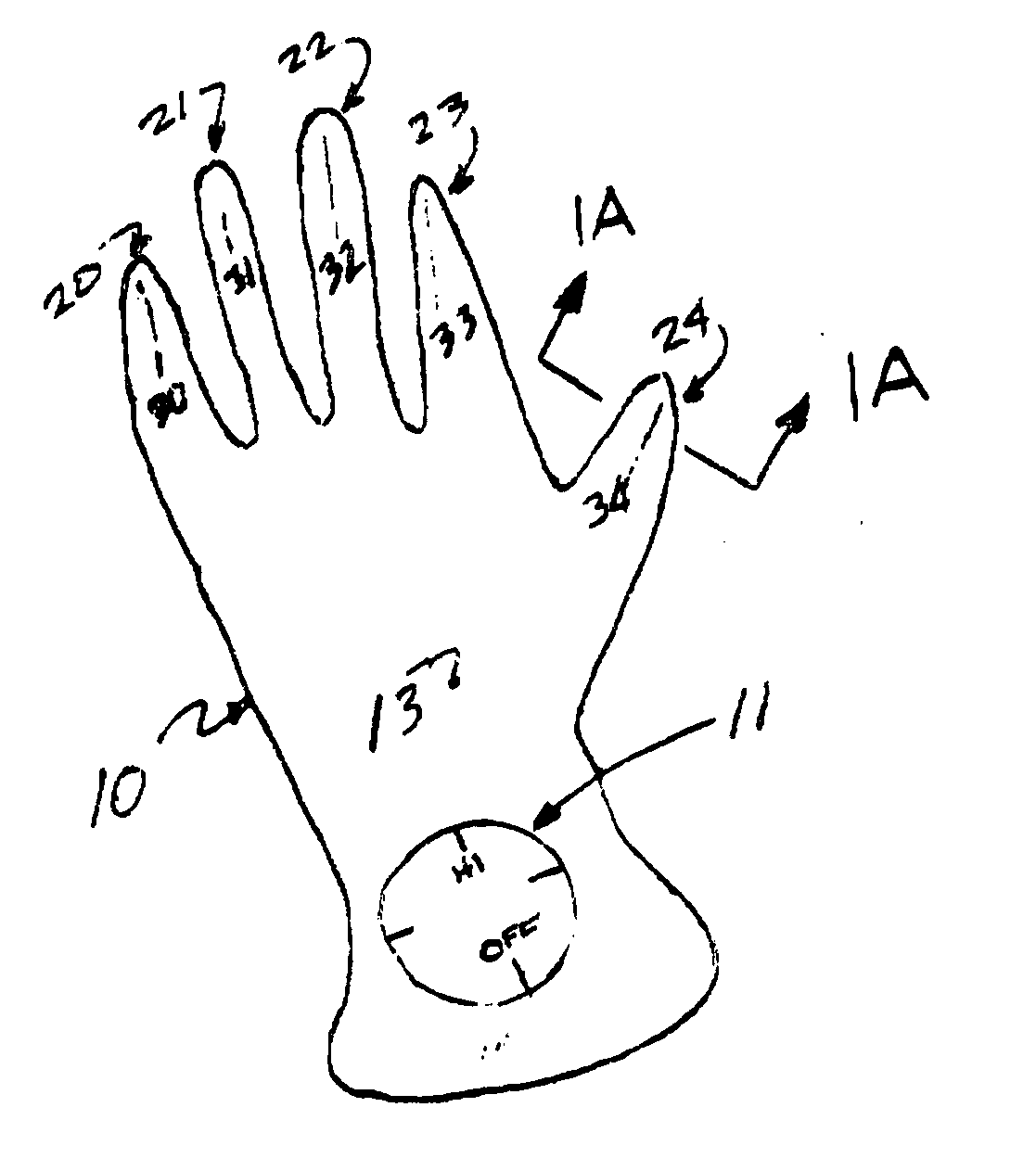
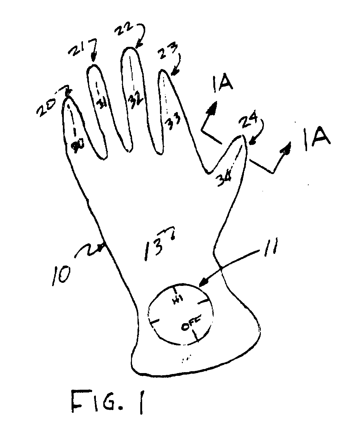
[0022] With reference to FIG. 1, 1A and 2, the therapeutic glove system 10 has slits 30, 31, 32, 33, 34 on the bottom 14 of exterior fingers 20, 21, 22, 23, 24. The exterior skin 13 of the therapeutic glove 10 is lined with insulation 40 to retain heat within the therapeutic system. A vibrator controller 11 is built on top of the exterior skin 13. The palm side 14 of glove 10 houses the pocket 12 for a vibrator motor and the pocket 15 for the battery pack 90.

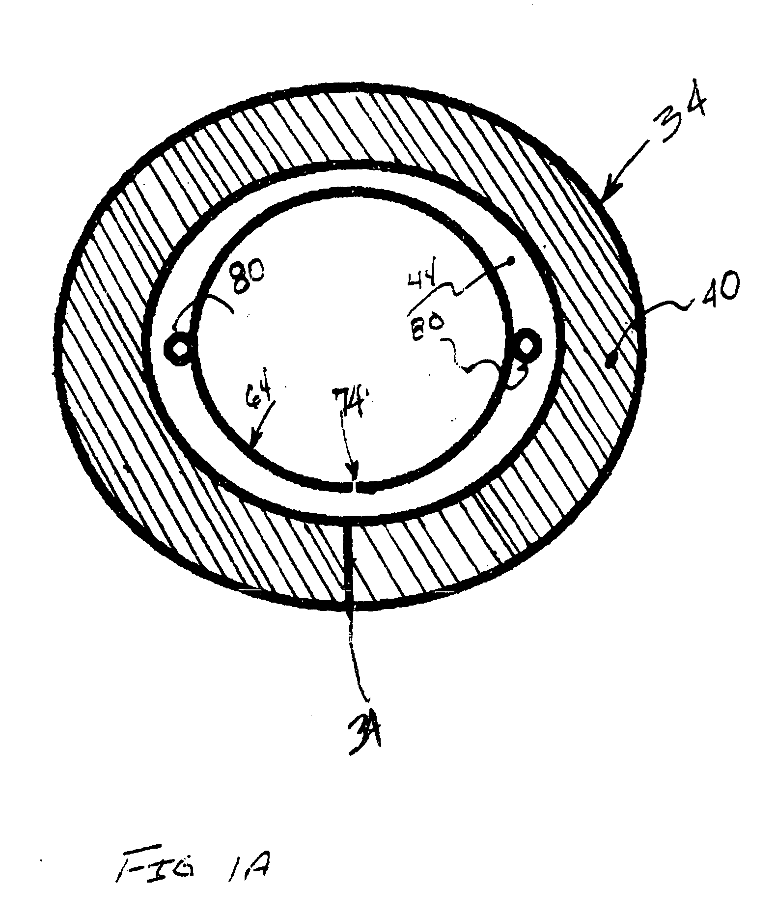
[0023] With reference to FIG. 1A, a cross-sectional area of thumb shows the thermodynamic workings of the glove. The exterior skin 13 is attached to insulation in order to retard heat flow to the outside of the glove system 10. An air gap 41 serves as a stagnant air barrier to further retard heat flow to the exterior of glove system 10. Strip heater 80 loops around the top of the interior glove 50 thereby transferring heat to a hand that is cooler than the heater

[0024] With reference to FIG. 3, the internal glove skin 50 distr...


PUM


Abstract

The Electrical Heat and Vibrating Device is a lightweight, portable, completely self-contained low voltage, and self-administered therapeutic apparatus. More particularly, this invention gives the wearer or user comforting sensations to facilitate a temporary reduction in joint stiffness, joint pain, and joint discomfort, within the human body.

Description

BACKGROUND OF THE INVENTION [0001] There is a need for a combined heating and vibrating apparatus that is portable and provided temporary pain relief to sufferers of inflammation of the joints, such as arthritis. [0002] Many people who have problems (reactions) obtaining temporary relief through drugs are very good candidates for temporary relief supplied by mechanical devices. [0003] Lack of portability and lack of self-administration were key problems past mechanical devices. This invention overcomes both of the above problems by drastically reducing the amount of heat needed and by providing a system that a patient can self-administer treatments as needed. [0004] By incorporating several previous inventions into one single device, this invention introduces a new class of devices that promotes self-administration, portability, lightweight, and monitoring. [0005] French patent 645,147 provided temporary relief by increasing blood flow through heat and massage therapy but it lacked ...

Claims


Application Information

Patent Timeline
Patent Type & Authority Applications(United States)
IPC IPC(8): A61H1/00
CPCA61H23/02A61H2201/0207A61H2205/065A61H2201/165A61H2201/0228
Inventor GROSS, JULIA
Owner GROSS JULIA
Why Eureka
Try Eureka