
Support system for intervertebral fusion

Inactive Publication Date: 2006-02-23
FOSTER-MILLER
View PDF31 Cites 151 Cited by
  • Summary
  • Abstract
  • Description
  • Claims
  • Application Information

AI Technical Summary

Benefits of technology

[0016] In the deployed state, the support system forms a geometric shape. It is envisioned that the deployed support system may be hexagonal, circular, pentagonal, linear, V-shaped, or another shape as required for the specific surgical procedure being performed. In addition, the heights of the support members may not be uniform such that the support system has a height differential between an anterior region and a posterior region. This height differential assists in maintaining a desired degree of lordosis between the adjacent vertebrae.
[0017] In one embodiment, a band may be included in the presently disclosed support system. The band is substantially fluid-tight and may be formed from the same material of the support system or another selected biocompatible material. The band substantially circumscribes the support system by forming a barrier wall along an interior or exterior perimeter of the support system. The band may be configured to have a uniform height generally equal to the height of the shortest support member. Alternatively, the band may be configured to have a variable height that conforms to the heights of the support members in the support system. In one embodiment, the band is inserted into the working space after the support system is in its second state and attached thereto to form the barrier wall. In an alternate embodiment, the band is attached to the support system and forms the barrier wall as the support system transitions into the second state. Alternative bone growth materials having fluid or plastic characteristics may be deposited into the working space since the band forms a substantially fluid-tight barrier wall that minimizes the leakage of these alternative materials.
[0018] Like conventional support systems, this device separates vertebrae in the spine and maintains proper spacing and structural integrity while the spine heals and fuses through and around the support system. This is needed, for example, in cases where back pain necessitates the removal of a spinal disc. With this device, the procedure can be performed in a minimally invasive or laparoscopic procedure, with all of the attendant benefits that such procedures afford.

Problems solved by technology

Both of these methods contribute to increased tissue trauma, either to ligaments and musculature in the former case, or to cartilage and vertebrae in the latter.
Damage to the ligaments and musculature results in greater postoperative discomfort and a longer healing time, while damage to the vertebral body may cause the implant to fail through subsidence or dislocation.
These procedures carry with them a unique set of challenges and potential complications, often stemming from the complexity of the method required to implant the device.
In addition, the heights of the support members may not be uniform such that the support system has a height differential between an anterior region and a posterior region.

Method used


Image

  • Support system for intervertebral fusion
  • Support system for intervertebral fusion
  • Support system for intervertebral fusion

Examples


Embodiment Construction

[0043] Embodiments of the presently disclosed support system for intervertebral fusion will now be described in detail with reference to the drawings, in which like reference numerals designate identical or corresponding elements in each of the several views. As used herein, the term “distal” refers to that portion of the instrument, or component thereof which is further from the user while the term “proximal” refers to that portion of the instrument or component thereof which is closer to the user.

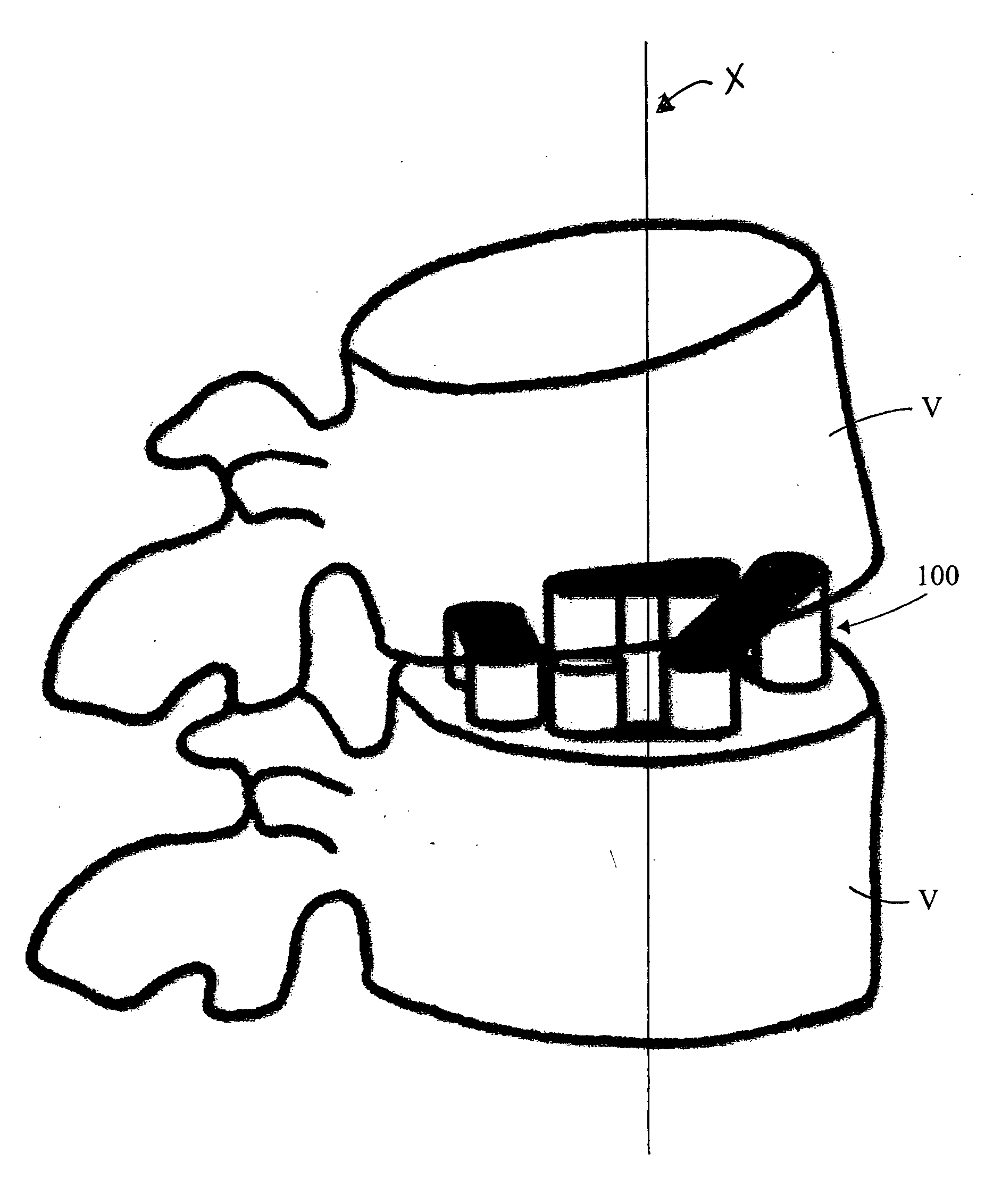
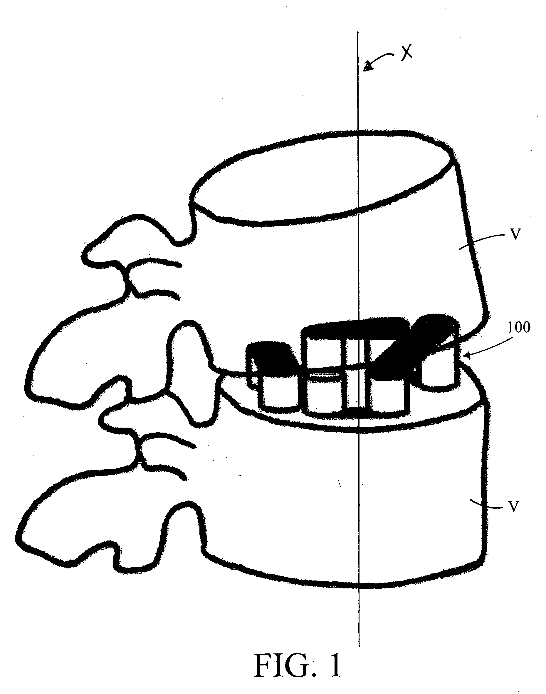
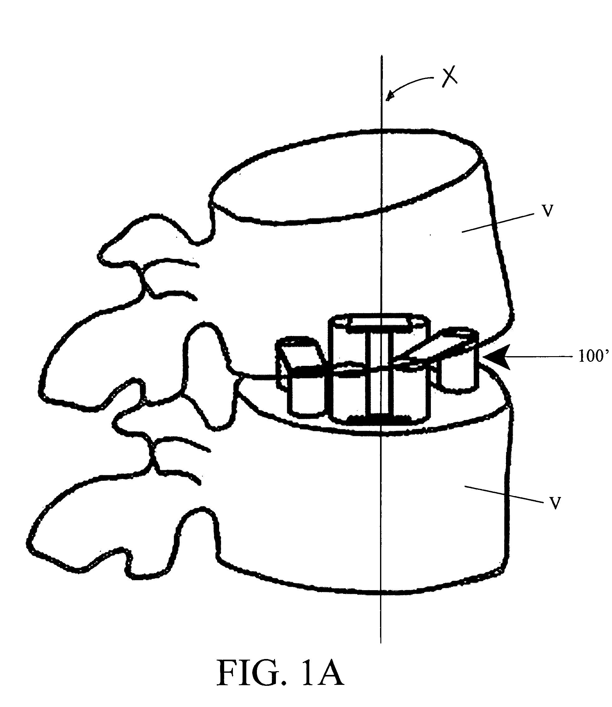
[0044] A support system 100, in accordance with one embodiment of the present disclosure, is illustrated in FIGS. 1 and 2. Support system 100 includes a plurality of vertical or support members 10 (FIG. 2) and a plurality of horizontal or cross members 20 (FIG. 2), wherein each cross member 20 is attached to a support member 10 using a hinge 30 (FIG. 4). Each support member 10 and each cross member 20 may be a solid structure. In such a configuration, the vertical and cross members 10, 2...


PUM


Abstract

A support system includes a plurality of support members and a plurality of cross members. The support system is adapted to fit within an access device for insertion into a space between adjacent vertebrae. A plurality of hinges connects each cross member to at least one support member. The support system is movable between a first state and a second state. In the first state, the support system is substantially linear. In the second state, the support system is configurable into one of several geometric shapes. A number of strings may be attached to the support members for transitioning the support system from the first state to the second state.

Description

CROSS-REFERENCE TO RELATED APPLICATIONS [0001] This application claims priority to, and the benefits of, U.S. Provisional Application Ser. No. 60 / 602,718, filed on Aug. 19, 2004, the entire contents of which are hereby incorporated by reference.BACKGROUND [0002] 1. Technical Field [0003] The present disclosure relates to devices for bone fusion and, more particularly, to a support system for intervertebral fusion. [0004] 2. Background of Related Art [0005] Clinicians throughout the developed world recognize the management of low back pain as a widespread problem. Almost three quarters of the U.S. population has at one time experienced low back pain, and about 4% of Americans require surgical intervention in their lifetime, some undergoing multiple procedures. Almost 700,000 spine procedures are performed each year in the United States, and the total cost incurred by back pain and treatment for it exceeds $50 billion per year. Back problems account for almost 30% of workers' compensa...

Claims


Application Information

Patent Timeline
IPC IPC(8): A61B17/56
CPCA61F2/30A61F2/4455A61F2/4465A61F2/4611A61F2002/2817A61F2002/2835Y10T16/52A61F2002/30471A61F2002/30616A61F2002/30919A61F2002/4415A61F2220/0091A61F2230/0065A61F2002/302
Inventor GALEA, ANNA M.
Owner FOSTER-MILLER
Learn More