Electroactive polymer-based actuation mechanism for linear surgical stapler

a linear surgical and actuation mechanism technology, applied in the field of surgical devices, can solve the problems of large force required to effect articulation and actuation, force change, and exceed the hand strength of surgeons

Active Publication Date: 2006-02-23
CILAG GMBH INT
View PDF12 Cites 122 Cited by
  • Summary
  • Abstract
  • Description
  • Claims
  • Application Information

AI Technical Summary

Benefits of technology

[0014] In yet another embodiment, a surgical stapler is provided having an elongate shaft with a linear staple applying assembly formed on a distal end thereof and adapted to receive tissue. The staple applying assembly is coupled to at least one electroactive polymer actuator that is configured to drive at least one linear row of staples into tissue when energy is delivered to the electroactive polymer actuator. In one exemplary embodiment, the staple applying assembly includes a stapling mechanism and an anvil opposed to the stapling mechanism. The stapling mechanism can include a plurality of drivers disposed therein and adapted to drive a plurality of staples from the stapling mechanism toward the anvil. The electroactive polymer actuator can be coupled to each of the plurality of drivers such that energy can be selectively delivered to at least one of the electroactive polymer actuators to move at least one of the drivers and thereby drive at least one staple into tissue. In another embodiment, a plurality of electroactive polymers can be disposed within the staple applying assembly, and each electroactive polymer can be effective to drive a linear row of staples into tissue when energy is delivered thereto. The electroactive polymers can be adapted to be individually actuated to drive a staple from the stapling mechanism toward the anvil.
[0016] A method for applying one or more surgical staples to tissue is also provided and can include capturing tissue between opposed first and second jaws, and delivering energy to an electroactive polymer actuator to drive at least one linear row of staples from the first jaw through the tissue and against an anvil formed on the second jaw. In one embodiment, one or more driver(s) can be movably disposed within the first jaw, and energy delivery to the electroactive polymer actuator can be effective to move the driver(s) within the first jaw to drive staples therethrough and against the anvil. In another embodiment, delivering energy to the electroactive polymer actuator can be effective to move a push rod distally to advance a plurality of staple drivers that drive at least one linear row of staples from the first jaw through the tissue and against an anvil formed on the second jaw. In other aspects, energy can be selectively delivered to a plurality of electroactive polymer actuators disposed within the first jaw to drive at least one linear row of staples from the first jaw through the tissue and against an anvil formed on the second jaw. In yet another embodiment, delivering energy to an electroactive polymer actuator can be effective to advance a blade distally to cut tissue being stapled.

Problems solved by technology

One drawback to current stapling devices is that a large force is required to effect articulation and actuation, and the force changes throughout the course of the firing stroke.
The large force necessary to effect articulation and actuation, as well as the variations in the force, can often exceed the surgeon's hand strength and could potentially result in binding or other malfunctions that may occur when an unexpectedly higher force is required.
The large force required to effect firing can also interfere with the flexibility or adjustability of the shaft.
The transfer of force from the handle to the end effector can necessarily interfere with the pivoted or curved orientation of the shaft, potentially causing it to straighten.

Method used


Image

  • Electroactive polymer-based actuation mechanism for linear surgical stapler
  • Electroactive polymer-based actuation mechanism for linear surgical stapler
  • Electroactive polymer-based actuation mechanism for linear surgical stapler

Examples


Embodiment Construction

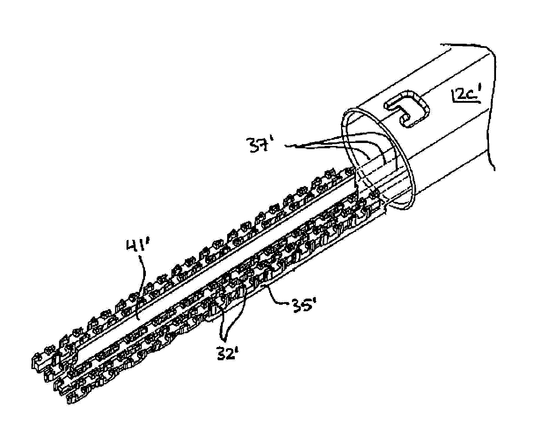
[0039] The present invention generally provides methods and devices for effecting movement of one or more components of a surgical stapler. In one exemplary embodiment, a surgical stapler is provided having a stapling mechanism or end effector that is movably coupled to a distal end of an elongate shaft. An electrically expandable and contractible actuator, such as an electroactive polymer actuator, can be used to pivotally or angularly adjust a position of the stapling mechanism relative to the elongate shaft by delivering energy to the electroactive polymer actuator. In another embodiment, an electroactive polymer actuator can be used to actuate the end effector, thereby driving one or more staples, and preferably at least two linear rows of staples, into tissue. The actuator can alternatively or additionally drive a blade distally to cut tissue being stapled. A person skilled in the art will appreciate that the surgical stapler can have a variety of configurations, and that the e...


PUM

PropertyMeasurementUnit
voltage potentialaaaaaaaaaa
sizeaaaaaaaaaa
energyaaaaaaaaaa

Abstract

Methods and devices are provided for actuating and / or articulating a surgical stapler. In one embodiment, a surgical stapler is provided having a stapling mechanism or end effector that is movably coupled to a distal end of an elongate shaft. An electrically expandable and contractible actuator, such as an electroactive polymer actuator, can be used to pivotally or angularly adjust a position of the stapling mechanism relative to the elongate shaft by delivering energy to the electroactive polymer actuator. In another embodiment, an electroactive polymer actuator can be used to actuate the staple applying assembly, thereby driving one or more staples, and preferably at least two linear rows of staples, into tissue. The actuator can alternatively or additionally drive a blade distally to cut tissue being stapled.

Description

CROSS REFERENCE TO RELATED APPLICATIONS [0001] This application is a continuation-in-part of U.S. patent application Ser. No. 11 / 082,495 filed on Mar. 17, 2005 and entitled “Surgical Instrument Incorporating an Electrically Actuated Articulation Mechanism,” which claims priority to U.S. Provisional Application No. 60 / 591,694 filed on Jul. 28, 2004 and entitled “Surgical Instrument Incorporating an Electrically Actuated Articulation Mechanism.” These applications are hereby incorporated by reference in their entireties.FIELD OF THE INVENTION [0002] The present invention relates broadly to surgical devices, and in particular to methods and devices for articulating and actuating a surgical stapler using electrically expandable and contractible actuators, such as electroactive polymers. BACKGROUND OF THE INVENTION [0003] Endoscopic surgical instruments are often preferred over traditional open surgical devices since a smaller incision tends to reduce the post-operative recovery time and...

Claims


Application Information

Patent Timeline
Patent Type & Authority Applications(United States)
IPC IPC(8): A61B17/28
CPCA61B17/07207A61B17/29A61B2017/00017A61B2017/2946A61B2017/00871A61B2017/07278A61B2017/2927A61B2017/00398
Inventor ORTIZ, MARK S.SHELTON, FREDERICK E. IVHUEIL, JOSEPH CHARLESSWAYZE, JEFFREY S.
Owner CILAG GMBH INT
Why Eureka
Try Eureka