This helps you quickly interpret patents by identifying the three key elements:
Problems solved by technology
Method used
Benefits of technology
[0035] The outputs of the DDC go to the TAL. Because it is possible for an instruction to be dependent on more than one previous instruction, the TAL must determine which of those previous instructions will be the last one to be executed. The present inv
Problems solved by technology
This problem is severe when the goal of register allocation is to keep as many values in as few registers as possible.
Keeping a large number of values in a small number of registers creates a large number of conflicts when the execution order is changed from the order assumed by the register allocator.
Storage conflicts constrain instruction issue and reduce performance.
Unfortunately, this approach runs into several problems.
Software does not always know the latency of processor operations, and thus, cannot always know how to arrange instructions to avoid dependencies.
If the processor is attempting to fetch several instructions per cycle, or if some operations take several cycles to complete, the number of no-ops required to prevent the processor from seeing dependent instructions rapidly becomes excessive, causing an unacceptable increase in code size.
When a processor permits out-of-order issue, it is not at all clear what mechanism software should use to
Method used
Image
Click on the blue label to locate the original text in one second.
Reading with bidirectional positioning of images and text.
Examples
Embodiment Construction
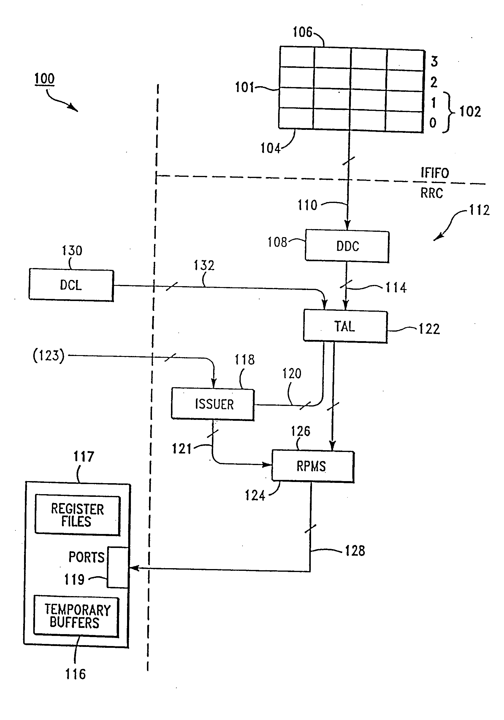
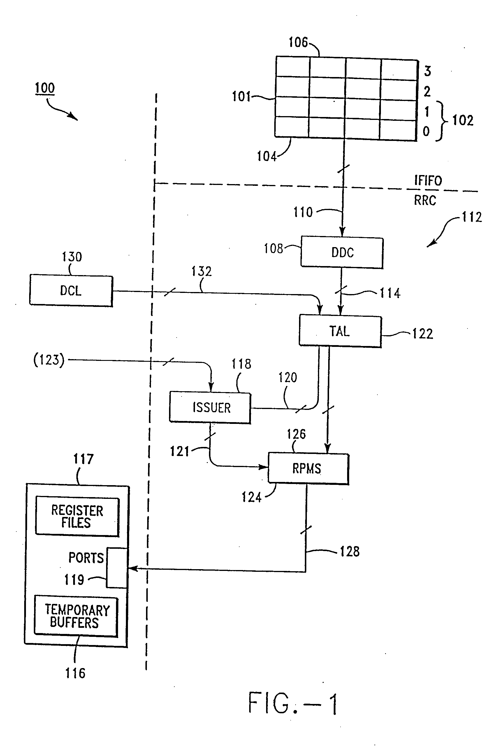
[0050]FIG. 1 shows a representative high level block diagram of an Instruction Execution Unit (IEU) 100 associated with the present invention. The goal of IEU 100 is to execute as many instructions as possible in the shortest amount of time. There are two basic ways to accomplish this: optimize IEU 100 so that each instruction takes as little time as possible or optimize IEU 100 so that it can execute several instructions at the same time.
[0051] Instructions are sent to IEU 100 from an Instruction Fetch Unit (IFU, not shown) through an instruction FIFO (first-in-first-out register stack storage device) 101 in groups of four called “buckets.” IEU 100 can decode and schedule up to two buckets of instructions at one time. FIFO 101 stores 16 total instructions in four buckets labeled 0-3. IEU 100 looks at an instruction window 102. In one embodiment of the present invention, window 102 comprises eight instructions (buckets 0 and 1). Every cycle IEU 100 tries to issue a maximum number o...
PUM
Abstract
A register renaming system for out-of-order execution of a set of reduced instruction set computer instructions having addressable source and destination register fields, adapted for use in a computer having an instruction execution unit with a register file accessed by read address ports and for storing instruction operands. A data dependance check circuit is included for determining data dependencies between the instructions. A tag assignment circuit generates one or more tags to specify the location of operands, based on the data dependencies determined by the data dependance check circuit. A set of register file port multiplexers select the tags generated by the tag assignment circuit and pass the tags onto the read address ports of the register file for storing execution results.
Description
CROSS-REFERENCE TO RELATED APPLICATIONS [0001] This application is a continuation of application Ser. No. 10 / 086,197, filed Mar. 1, 2002, now allowed, which is a continuation of application Ser. No. 09 / 906,099, filed Jul. 17, 2001, now abandoned, which is a continuation of application Ser. No. 09 / 329,354, filed Jun. 10, 1999, now U.S. Pat. No. 6,289,433, which is a continuation of application Ser. No. 08 / 990,414, filed Dec. 15, 1997, now U.S. Pat. No. 5,974,526, which is a continuation of application Ser. No. 08 / 594,401, filed Jan. 31, 1996, now U.S. Pat. No. 5,737,624, which is a continuation of application Ser. No. 08 / 219,425, filed Mar. 29, 1994, now U.S. Pat. No. 5,497,499, which is a continuation of application Ser. No. 07 / 860,719, filed Mar. 31, 1992, now abandoned. The disclosures of each of the above-referenced applications are incorporated herein by reference. [0002] The following are related applications: “Semiconductor Floor Plan and Method for a Register Renaming Circuit...
Claims
Application Information
Patent Timeline
Application Date:The date an application was filed.
Publication Date:The date a patent or application was officially published.
First Publication Date:The earliest publication date of a patent with the same application number.
Issue Date:Publication date of the patent grant document.
PCT Entry Date:The Entry date of PCT National Phase.
Estimated Expiry Date:The statutory expiry date of a patent right according to the Patent Law, and it is the longest term of protection that the patent right can achieve without the termination of the patent right due to other reasons(Term extension factor has been taken into account ).
Invalid Date:Actual expiry date is based on effective date or publication date of legal transaction data of invalid patent.