Data processing device

a data processing and data technology, applied in the field of data processing devices, can solve the problems of deteriorating processing efficiency of the processor, various scheduling restrictions,

Inactive Publication Date: 2005-03-08
RENESAS ELECTRONICS CORP
View PDF21 Cites 44 Cited by
  • Summary
  • Abstract
  • Description
  • Claims
  • Application Information

AI Technical Summary

Problems solved by technology

Conventionally, in a microprocessor for executing sequentially a plurality of instructions by pipelines, execution of branch instruction is one reason for deteriorating processing efficiency of the processor because it disturbs the pipelines.
However, there were various restrictions on the scheduling depending on a type of instruction.

Method used


Image

  • Data processing device
  • Data processing device
  • Data processing device

Examples


embodiment 1

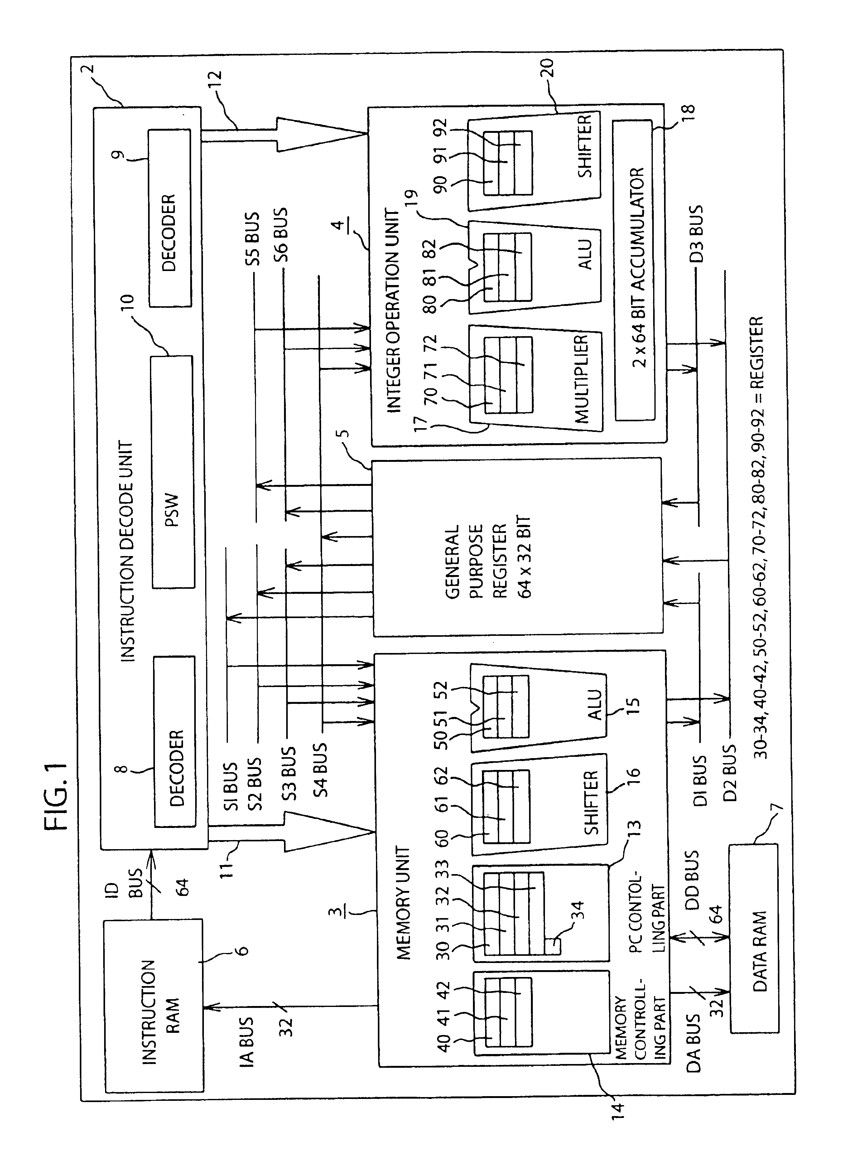
FIG. 1 is a block chart for showing a constitution of a microprocessor according to Embodiment 1 of the present invention. This microprocessor is a 32-bit microprocessor having an internal data bus of 32 bits. In this Figure, reference numeral 2 designates an instruction decode unit (instruction decoder) for performing a process of decoding an instruction code inputted from an instruction RAM 6 through an ID bus having a width of 64 bits; reference numeral 3 designates a memory unit (instruction execution unit) for performing an address calculation; reference numeral 4 designates an integer operation unit (instruction execution unit) for performing an arithmetic logic operation and / or a shift operation; reference numeral 5 designates a general purpose register of 32 bits×64 words; and reference numeral 7 designates a data RAM for storing data.

In the instruction decode unit 2, reference numerals 8 and 9 respectively designate decoders which decode an instruction code; and reference n...

embodiment 2

FIG. 12 shows a constitution of a microprocessor other than that shown in FIG. 1.

In this microprocessor, a register 43 and a memory circuit 44 are provided in a memory controlling part 14; a register 53 and a memory circuit 54 are provided in ALU 15; a register 63 and a memory circuit 64 are provided in a shifter 16; a register 73 and a memory circuit 74 are provided in a multiplier 17; a register 83 and a memory circuit 84 are provided in ALU 19; and a register 93 and a memory circuit 94 are provided in a shifter 20. A part of the constitution which has not been described in the above is the same as that shown in FIG. 1.

In the microprocessor shown in FIG. 1, the operation sub-instruction having a delay function, namely an operation sub-instruction which executes the operation at a clock cycle positioned after a clock cycle for judging a condition, is only a branch sub-instruction and a jump sub-instruction. However, it is possible to add a delay function to arbitrary operation sub-...


PUM


Abstract

A data processing device having a PC controlling part for executing an operation of branch which has a first register for holding a result of decoding in an instruction decode unit, a register for holding a description indicating an execution condition of the operation (a value of field for designating condition), and a register for holding the description indicating a time for executing the operation (an address value of PC), wherein the execution condition is started when a value held in the register is in agreement with a PC value in accordance with the description of the register; and if the condition is satisfied, the PC controlling part executes the operation based on a content held in the register, whereby it is possible to delay the time for judging the execution condition during this delay, to thereby increase a degree of freedom in scheduling instructions such that the branch instruction is positioned prior to the operation instruction for determining the execution condition in the program.

Description

FIELD OF THE INVENTIONThe present invention relates to a data processing device for properly scheduling conditional operation instructions in a program sequence.DISCUSSION OF BACKGROUNDConventionally, in a microprocessor for executing sequentially a plurality of instructions by pipelines, execution of branch instruction is one reason for deteriorating processing efficiency of the processor because it disturbs the pipelines. In order to prevent the processing performance from deteriorating, for example, a technique of using a delay slot is proposed.A case that a programmer makes the following instruction sequence 1 will be described.[Instruction Sequence 1](I0) CMPEQ r10, r11(I1) ADD r1, r2(I2) BRA F0=1 H′1000(I3) . . .(I4) . . .An instruction I0 is a comparison instruction for setting a flag F0 if a register 10 and a register 11 are equal as a result of a comparison therebetween. An instruction I1 is an add instruction for writing the addition of a content of register r1 and a conte...

Claims


Application Information

Patent Timeline
Patent Type & Authority Patents(United States)
IPC IPC(8): G06F9/38G06F9/32
CPCG06F9/30072G06F9/30058
Inventor YOSHIDA, TOYOHIKOFUJII, HIDEYUKI
Owner RENESAS ELECTRONICS CORP
Why Eureka
Try Eureka