Fuel routing structure for a V-type engine

a technology of fuel routing and v-type engines, which is applied in the direction of machines/engines, liquid fuel feeders, combustion air/fuel-air treatment, etc., can solve the problems of troublesome maintenance of the structure, achieve compact fuel routing structure, reduce the number of parts, and facilitate assembly and maintenance.

Active Publication Date: 2006-03-02
HONDA MOTOR CO LTD
View PDF9 Cites 32 Cited by
  • Summary
  • Abstract
  • Description
  • Claims
  • Application Information

AI Technical Summary

Benefits of technology

[0012] According to the first aspect of the invention, since fuel is supplied to each fuel injection valve using the fuel rail, fewer parts are required and the fuel routing structure is made compact. That is, by connecting the single fuel rail common to the fuel injection valves to the fuel injection valves individually corresponding to the intake ports of the cylinder heads of both banks, and because the fuel rail is connected to each fuel injection valve over the intake manifold, operability in assembly and in maintenance is enhanced. In addition, because the fuel rail is directly attached to the intake manifold, a dedicated member for supporting the fuel rail is not required and the number of parts is further reduced.
[0013] According to the second aspect of the invention, the attachment and the detachment of the fuel rail to / from the intake manifold are facilitated and operability in assembly and in maintenance is further enhanced.
[0014] According to the third aspect of the invention, not only is the connection structure of the fuel hose to the fuel rail facilitated but work for connecting the fuel hose to the fuel rail can be facilitated.
[0015] Further, according to the fourth aspect of the invention, as fuel is not returned from the fuel rail, a return pipe is not required and the fuel routing structure is simplified and small in size.

Problems solved by technology

Thus, a large number of parts are required for the structure, the fuel routing structure is intricate, and in addition, assembly and maintenance of the structure is troublesome.

Method used


Image

  • Fuel routing structure for a V-type engine
  • Fuel routing structure for a V-type engine
  • Fuel routing structure for a V-type engine

Examples


Embodiment Construction

[0025] Referring to the attached drawings, a number of selected illustrative embodiments of the present invention will be described below. It should be understood that only structures considered necessary for clarifying the present invention are described herein. Other conventional structures, and those of ancillary and auxiliary components of the system, are assumed to be known and understood by those skilled in the art.

[0026] FIGS. 1 to 5 show a fuel and air routing structure according to a first embodiment of the invention, FIGS. 6 and 7 show a fuel and air routing structure according to a second embodiment, and FIG. 8 shows a fuel and air routing structure according to a third embodiment.

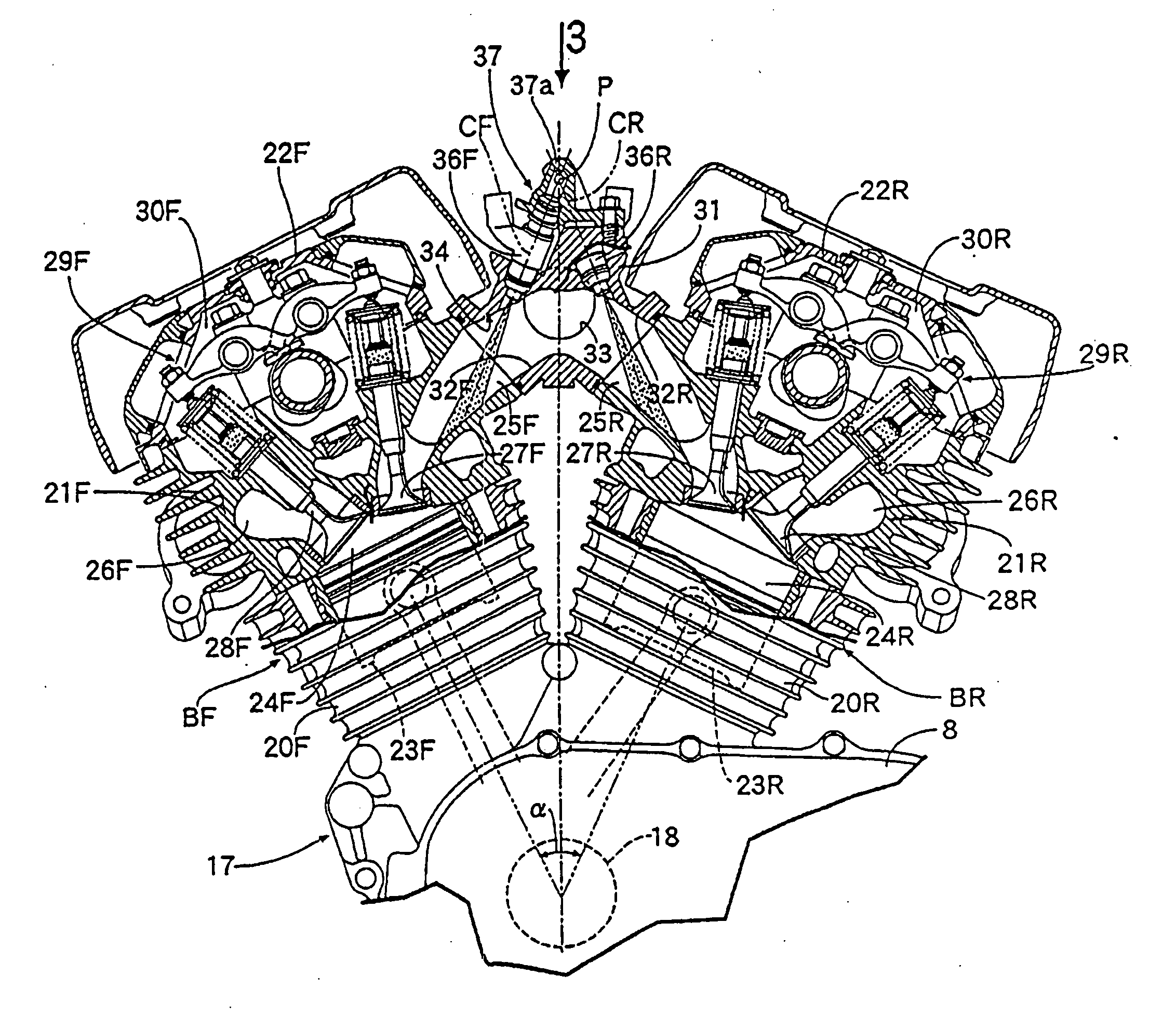
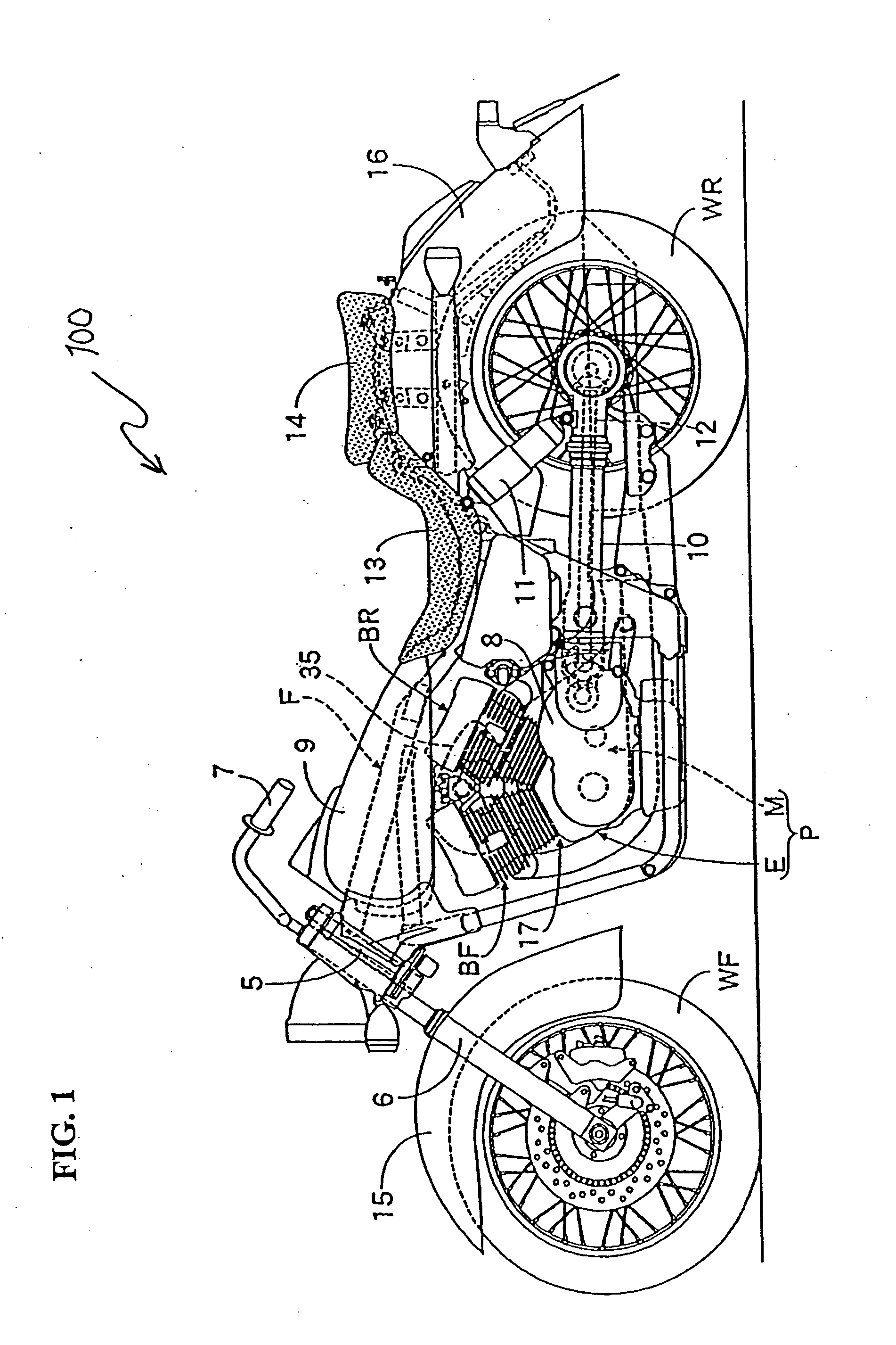
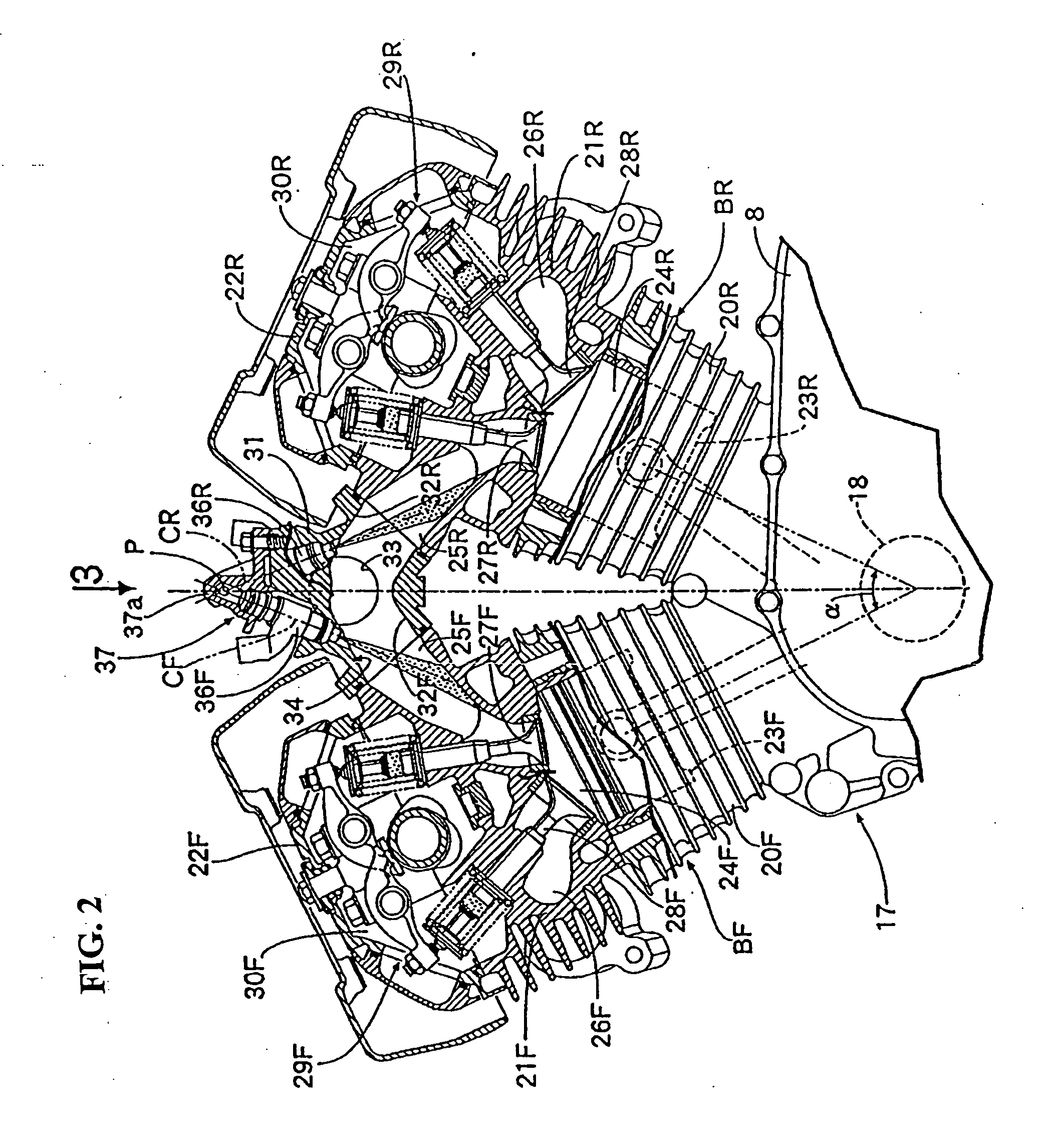
[0027] A motorcycle 100 having a body frame F, with a V-type engine E mounted transversely thereon, is shown in side elevational view in FIG. 1. The engine E of the motorcycle incorporates an intake manifold 31 therein for routing fuel and air, according to a first embodiment of the present in...


PUM


Abstract

A fuel routing structure for use in a vehicle having a V-type engine is provided. The structure has fewer parts, is compact, and facilitates ease of assembly and maintenance for a vehicle where fuel injection valves are attached to an intake manifold, which contains an intake passage communicating with intake ports of a pair of cylinder banks. Each fuel injection valve is attached to an upper part of the intake manifold, so that center lines of the fuel injection valves corresponding to both banks are crossed at an intersection over the intake manifold when a vehicle is viewed from the side. A fuel rail is provided with a fuel passage pipe, the axis of which is arranged in the vicinity of the intersection of the center lines of the fuel injection valves. The axis of the fuel passage pipe may be parallel to the crankshaft and may extend linearly and connected to all the fuel injection valves.

Description

CROSS-REFERENCE TO RELATED APPLICATIONS [0001] The present application claims priority under 35 USC 119 based on Japanese patent application No. 2004-246196, filed Aug. 26, 2004. The subject matter of this priority document is incorporated by reference herein. BACKGROUND OF THE INVENTION [0002] 1. Field of the Invention [0003] The present invention relates to a fuel and air routing structure for a V-type engine in a vehicle, the engine including cylinder heads provided in longitudinally arranged V-shaped banks. The fuel routing structure includes a member forming an intake passage communicating with intake ports of cylinder heads arranged between the pair of banks. Fuel injection valves for injecting fuel into the intake passage corresponding to each intake port are attached to the intake manifold. [0004] 2. Description of the Background Art [0005] The fuel routing structure of a V-type engine for a vehicle in which fuel injection valves corresponding to each cylinder in cylinder he...

Claims


Application Information

Patent Timeline
Patent Type & Authority Applications(United States)
IPC IPC(8): F02M69/46
CPCF02B31/04F02B31/085F02D9/109F02D9/14F02D9/16F02M35/10072Y02T10/146F02M35/116F02M35/162F02M61/145F02M69/462F02M69/465F02M35/10216Y02T10/12
Inventor HOTTA, KAZUHITOMINATO, HIRAKU
Owner HONDA MOTOR CO LTD
Why Eureka
Try Eureka