Welding machine and relative operating method

a welding machine and operating method technology, applied in the direction of soldering apparatus, manufacturing tools, auxillary welding devices, etc., can solve the problems of increasing the cost of servicing and repairing the machine, increasing the cost of the cooling unit, and affecting the service life of the cooling unit. , to achieve the effect of removing the respective drawbacks

Active Publication Date: 2006-03-02
ITW WELDING PRODS ITAL
View PDF25 Cites 9 Cited by
  • Summary
  • Abstract
  • Description
  • Claims
  • Application Information

AI Technical Summary

Benefits of technology

[0015] It is an object of the present invention to provide a welding machine which has all the advantages of both “compact” w

Problems solved by technology

On the other hand, maintenance of the cooling unit of “compact” welding machines of the type described above is extremely awkward.
That is, because of the extremely small amount of space between the electric cables and the highly electrically conductive component parts or conduits of the cooling circuit, repair of individual component parts of the cooling unit is extremely complicated and dangerous.
Any maintenance or repair of the cooling unit therefore calls for skilled technicians qualified to work in high-risk, electric discharge environments, thus increasing the cost of servicing and repairing the machine.
Moreover, to service or repair the cooling unit, the welding unit in some cases must be sent to specialized service facilities,

Method used


Image

  • Welding machine and relative operating method
  • Welding machine and relative operating method
  • Welding machine and relative operating method

Examples


Embodiment Construction

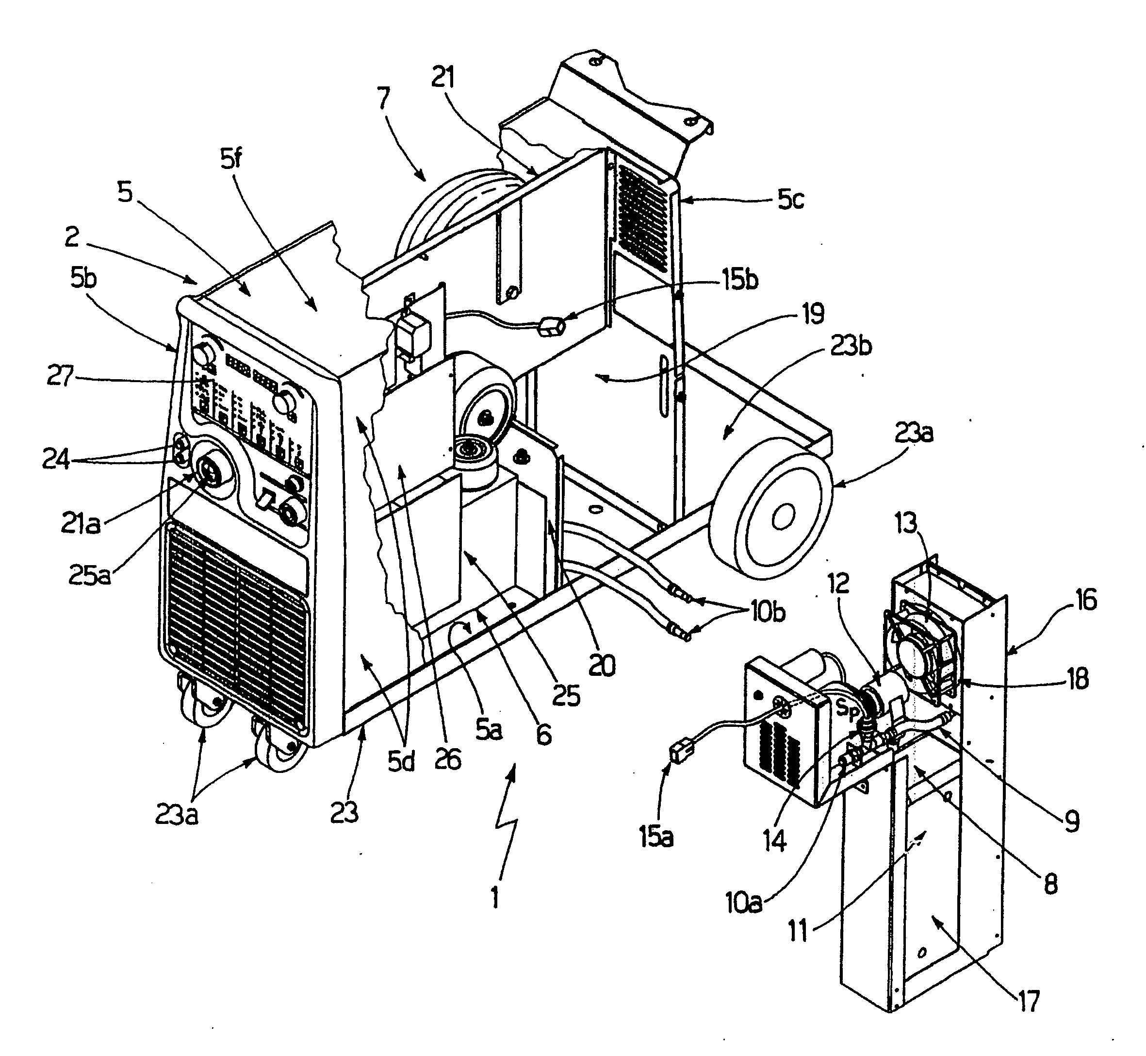
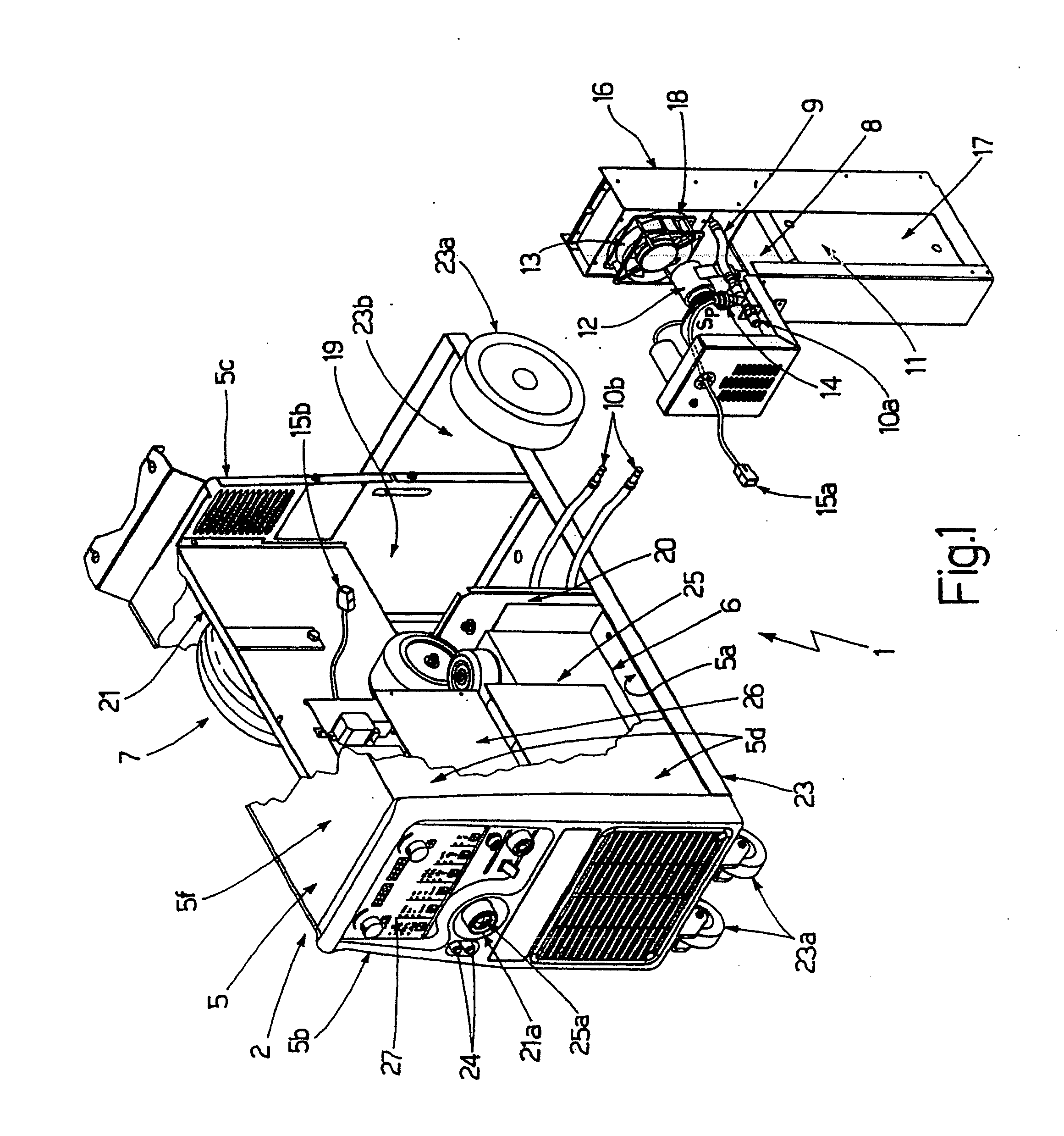
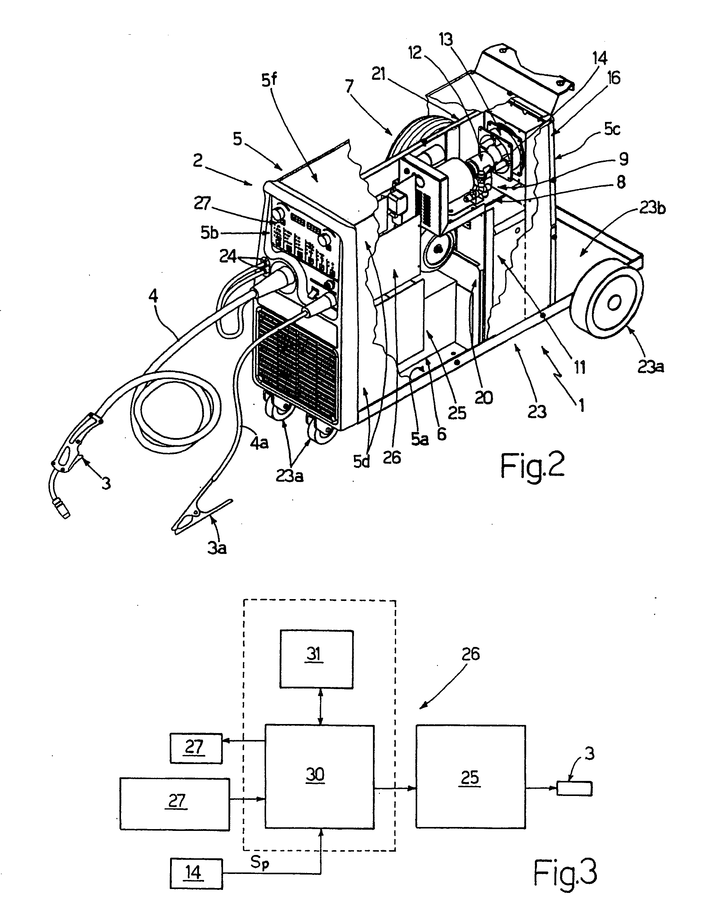
[0023] With reference to FIGS. 1 and 2, number 1 indicates as a whole a welding machine comprising a welding unit 2 for generating voltage / current for a given welding process, and at least one welding tool 3 (shown in FIG. 2) comprising a welding gun or torch and connectable to welding unit 2 by a cable 4 of given length, which supplies it with the voltage / current by which to generate the electric welding arc.

[0024] Welding unit 2 also comprises a ground cable 4a (FIG. 2) for grounding the work and connectable to an electric connector on welding unit 2; and a ground clip 3a connected to the opposite end of the ground cable and fixed, in use, to the work to close the welding circuit.

[0025] Welding unit 2 comprises a protective casing 5 (shown partly in FIGS. 1 and 2) in which are housed an electric power generating circuit 6 for generating the voltage / current for the selected welding process; preferably, though not necessarily, a wire-feed assembly 7 which, on command, feeds the we...


PUM

PropertyMeasurementUnit
Temperatureaaaaaaaaaa
Pressureaaaaaaaaaa
Electric potential / voltageaaaaaaaaaa

Abstract

A welding machine having a welding unit for generating a welding voltage/current, and at least one welding tool connectable to the welding unit by a cable and supplied by the cable with welding voltage/current; the welding unit has a closed protective casing, and a cooling unit for cooling the welding tool and/or cable on command; and the welding machine also has a modular unit containing the cooling unit and insertable stably and in easily removable manner inside the casing which is closed for protection of the welding unit, so as to be easily extracted and detached from the casing.

Description

[0001] The present invention relates to a welding machine and relative operating method. [0002] More specifically, the present invention relates to a welding machine for MIG (Metal Inert Gas) welding using a continuous wire in inert gas and pulsating or non-pulsating current supply; and / or MAG (Metal Active Gas) welding; and / or TIG (Tungsten Inert Gas) welding using a non-consumable tungsten electrode in inert gas; and / or STICK or MMA (Metal Manual Arc) welding; or multiprocess welding for selectively performing any one of the MIG, MAG, TIG, STICK welding processes; to which use the following description refers purely by way of example. BACKGROUND OF THE INVENTION [0003] As is known, known welding machines comprise a welding unit having a number of electric connectors supplied with a predetermined welding voltage / current; and a hand-held welding tool defined by a welding gun or torch and connected electrically by a power cable to the electric connectors on the welding unit, which su...

Claims


Application Information

Patent Timeline
IPC IPC(8): B23K9/10
CPCB23K9/1006B23K9/133B23K9/285B23K9/32B23K37/003
Inventor MARTIN, ALBERTOLOWTHER, MARKORLANDI, ROBERTO
Owner ITW WELDING PRODS ITAL
Why Eureka
Try Eureka