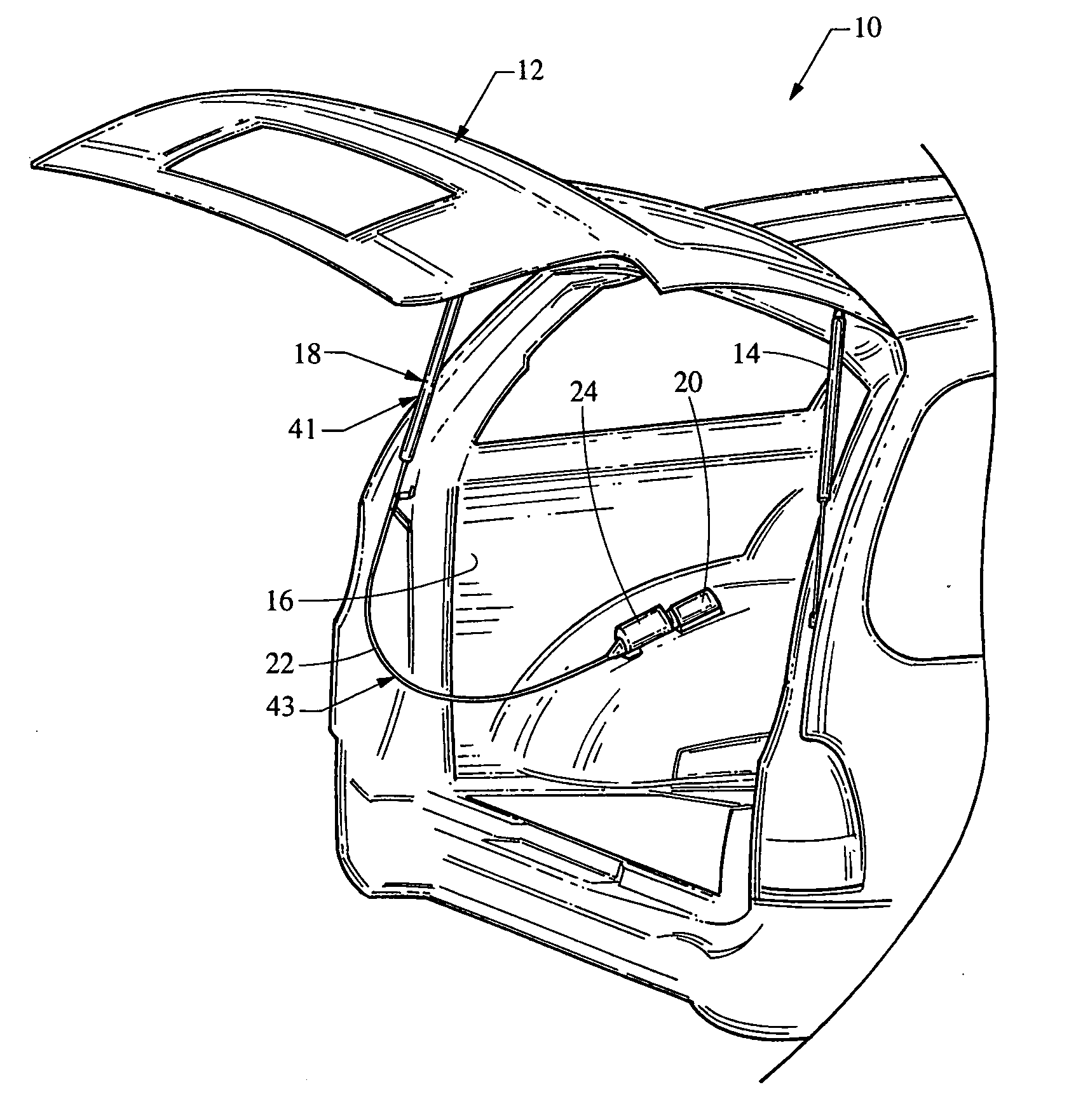
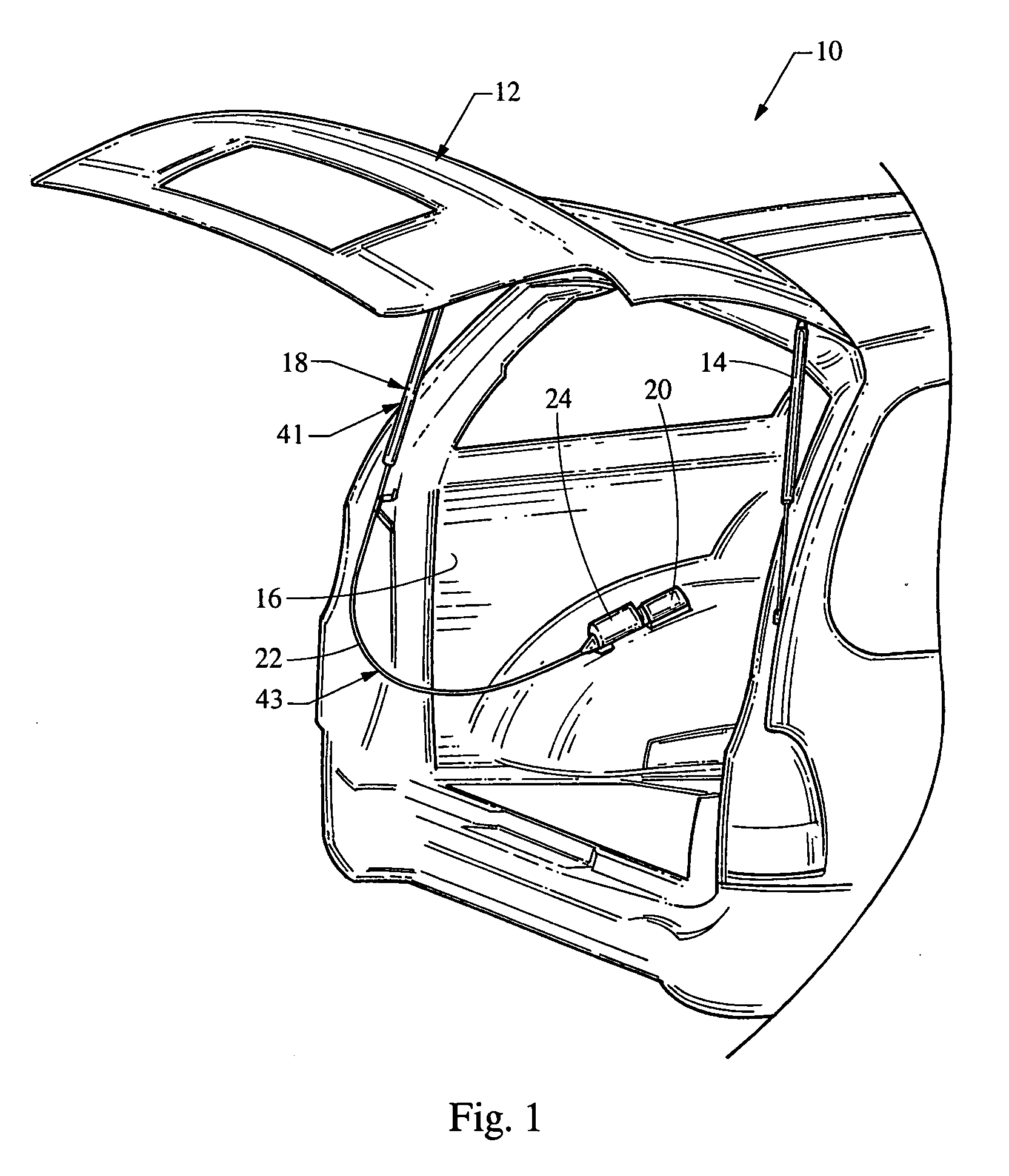
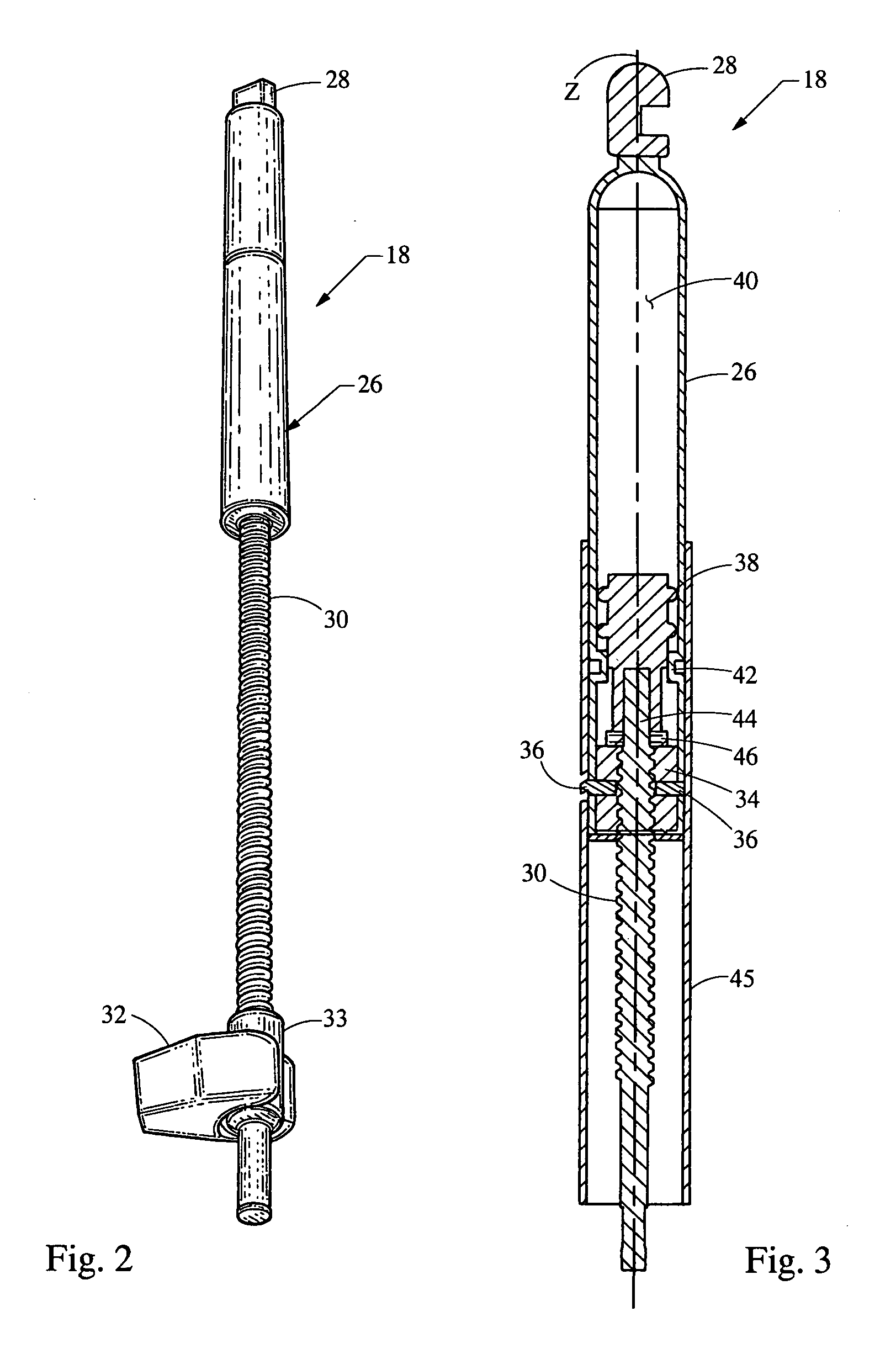
Integrated spring actuator strut assembly
a technology of actuator struts and springs, which is applied in the field of assembly, can solve the problems of loss of the precise relationship between the rotational position of the thread rod and the position of the closure panel
- Summary
- Abstract
- Description
- Claims
- Application Information
AI Technical Summary
Benefits of technology
Problems solved by technology
Method used
Image
Examples
first embodiment
[0032] such a releasable coupler 47 is described with reference to FIG. 4. As illustrated, retainer 48 is coupled with plunger 38 (not shown in FIG. 4) and includes an internal hollow socket 50. In this embodiment, rod drive end 44 includes groove 52. Socket 50 incorporates engagement elements in the form of inwardly deflecting fingers or tabs 54. Insertion of drive end 44 into socket 50 causes fingers 54 to be initially deflected in a radially outward manner, and further insertion causes them to snap into position engaging with groove 52. Once assembled in this manner, the parts are locked together and the rod 30 can exert pushing and pulling forces on plunger 38. As mentioned previously, it is desirable to further allow these components to be disassembled as required. Release ring 56 is provided to enable such disconnection. In the normal position of release ring 56, it is retracted relative to drive end 44. When it is desired to disassemble these components, release ring 56 is pu...
second embodiment
[0033] With reference to FIG. 6, a coupler 60 is shown. In this instance, retainer 62 includes a projecting barrel or tube which is split to form a number of engagement elements in the form of fingers 64 with inwardly directed teeth or barbs 66. Insertion of rod drive end 68 causes the barbs 66 to initially be deformed in a radially outward direction until they can snap into engagement with groove 70. Coupler 60 further incorporates release ring or bushing 76. Release bushing 76 includes a forward edge which is conically tapered. As shown in FIG. 7, depressing release bushing 76 into engagement with fingers 64 causes them to be expanded in a radially outward direction, releasing the interengagement between barbs 66 and grooves 70. This embodiment of coupler 60 further incorporates an anti-friction thrust bearing in the form of ball 72 which contacts bearing plate 74. Since the contact between ball 72 and bearing plate 74 is essentially point contact, very little torque is transmitte...
third embodiment
[0034] coupler 80 is shown with reference to FIG. 8. In this instance, retainer 82 includes engagement elements in the form of fingers 86 having inwardly directed barbs 88, similar to those described in connection with coupler 60. In a similar fashion, depressing rod drive end 90 into retainer 82 causes fingers 86 to be expanded outwardly until barbs 88 engage with groove 92. This embodiment of a coupler differs from the previously embodiments in that nut 94 is modified to incorporate a projecting conical extension 96. Coupler 80 can be disengaged simply by advancing nut 94 to a position causing conical end 96 to engage with fingers 86, causing them to expand in a manner similar to the previous embodiments.
[0035] An alternate embodiment of integrated spring actuator strut assembly 102 is shown with reference to FIGS. 10 and 11. This second embodiment differs from strut assembly 18 in that gas strut cylinder 104 is of generally conventional internal construction, utilizing internal p...
PUM
 Abstract
Description
Claims
Application Information
 - R&D
- Intellectual Property
- Life Sciences
- Materials
- Tech Scout
- Unparalleled Data Quality
- Higher Quality Content
- 60% Fewer Hallucinations
Browse by: Latest US Patents, China's latest patents, Technical Efficacy Thesaurus, Application Domain, Technology Topic, Popular Technical Reports.
© 2025 PatSnap. All rights reserved.Legal|Privacy policy|Modern Slavery Act Transparency Statement|Sitemap|About US| Contact US: help@patsnap.com


