Electromotive power steering system

a technology of power steering system and motor controller, which is applied in the direction of electronic commutators, dynamo-electric gear control, dynamo-electric converter control, etc., can solve the problem that the concrete practical method of abnormality judgment is not described at all, and achieve the effect of preventing abnormal power-assisted steering and preventing wrong judgment due to the effect of induced voltage generated by the motor rotating

Active Publication Date: 2006-03-02
MITSUBISHI ELECTRIC CORP
View PDF8 Cites 32 Cited by
  • Summary
  • Abstract
  • Description
  • Claims
  • Application Information

AI Technical Summary

Benefits of technology

[0025] In an electromotive power steering system according to a ninth aspect of the present invention, application of current to the motor is shut off if the abnormality judging unit judges that a system-control abnormality has occurred; thereby, abnormal power-assisted steering can be prevented.
[0026] In an electromotive power steering system according to a tenth aspect of the present invention, the abnormality judgment is forbidden when the rotational speed of the motor is equal to or higher than a predetermined value; thereby, a wrong judgment due to the effect of induced voltages generated by the motor rotating can be prevented.

Problems solved by technology

However, in the above described patent document 1, any concrete practical method for the abnormality judgment is not described at all.

Method used


Image

  • Electromotive power steering system
  • Electromotive power steering system
  • Electromotive power steering system

Examples


Embodiment Construction

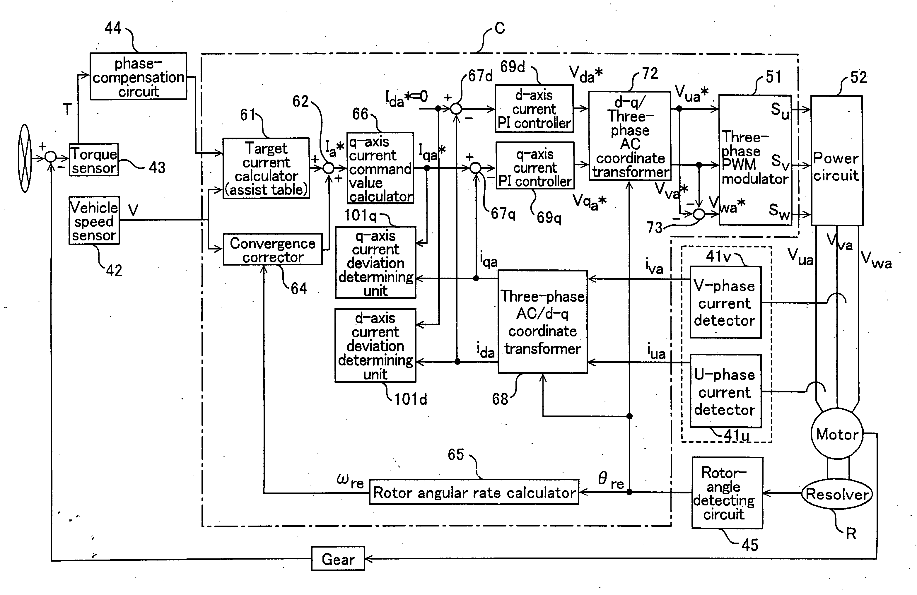
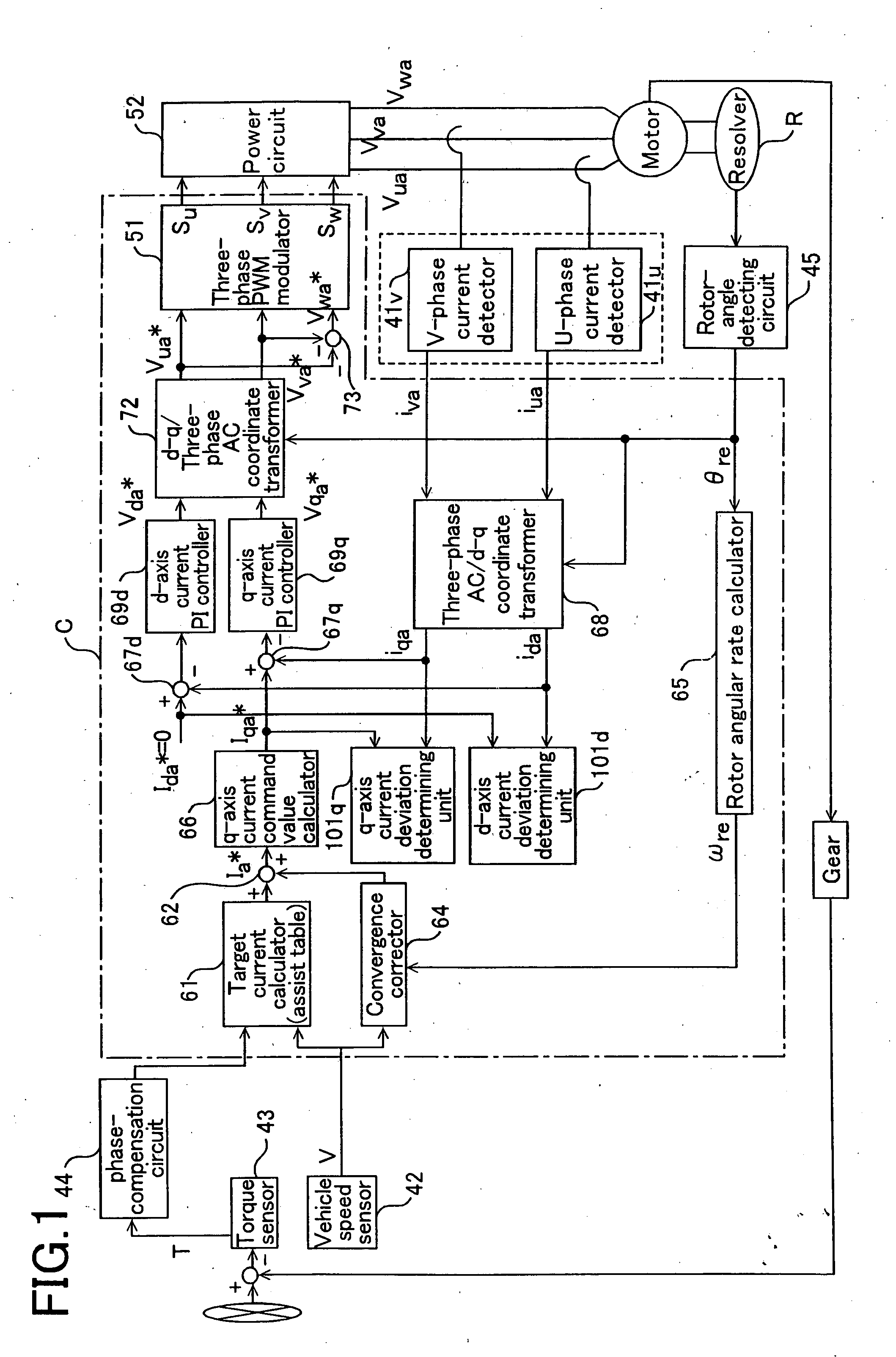
[0036] Hereinafter, an embodiment according to the present invention will be explained in detail. FIG. 1 is a block diagram for explaining a functional configuration of a motor M used for an electromotive power steering system according to the present invention. Here, blocks, in FIG. 1, given the same numerals as those in FIG. 9 operate similarly to the blocks illustrated in FIG. 9; therefore, their detailed explanations are omitted.

[0037] In this embodiment, in order to realize a means for determining whether a convergence-compensated target-current command value Ia* calculated by adding a target current command value Ia* specified in a target current calculator 61 and a convergence compensation value Ico* of current is correctly applied into the motor M, a d-axis current deviation determining unit 101d and a q-axis current deviation determining unit 101q are provided. A d-axis current command value ida* and a d-axis current detection value ida obtained through a three-phase AC / d-...


PUM


Abstract

An objective is to provide, in a motor controller used for an electromotive power steering system, a concrete realistic method for easily performing abnormality judgments in its control system. The electromotive power steering system includes: a d-q command value setting unit for determining, for current to be applied to the motor, d-axis and q-axis current command values in a d-q coordinate system; a current detector for detecting a three-phase AC current actually flowing in the motor; a three-phase AC/d-q coordinate transformer for transforming the three-phase AC current detected by the current detector into a d-axis current detection value and a q-axis current detection value in the d-q coordinate system; a voltage controller for controlling a voltage applied to the motor, based on the d-axis current command value and the q-axis current command value, and on the d-axis current detection value and the q-axis current detection value; and an abnormality judging unit for judging, by either comparing the q-axis current command value with the q-axis current detection value, or comparing the d-axis current command value with the d-axis current detection value, whether a system-control abnormality has occurred.

Description

BACKGROUND OF THE INVENTION [0001] 1. Field of the Invention [0002] The present invention relates to motor controllers for electromotive power steering systems that perform power-assisted steering by applying torque generated by a motor to a steering mechanism. [0003] 2. Description of the Related Art [0004] An electromotive power steering system has conventionally been known, in which torque generated by a motor such as a three-phase brushless motor is transmitted to a steering mechanism, thus power-assisted steering is performed. [0005] [Patent document 1] Japanese Laid-Open Patent Publication 187,578 / 2001. [0006] Relationships between a motor M for assisting this electromotive power steering system and a microcontroller C for controlling the motor M are illustrated in FIG. 7, and a block diagram representing a functional configuration of a motor controller for a conventional electromotive power steering system is illustrated in FIG. 8. [0007]FIG. 8 represents the relationships am...

Claims


Application Information

Patent Timeline
Patent Type & Authority Applications(United States)
IPC IPC(8): H02P7/00B62D5/04H02P6/06H02P6/08H02P6/12H02P6/17H02P6/28H02P21/00H02P21/22H02P27/04H02P27/08
CPCB62D5/0481B62D5/0493B62D5/0487B62D5/0406B62D5/0409
Inventor KIFUKU, TAKAYUKIKOZUKI, HIROYUKIMATSUSHITA, MASAKI
Owner MITSUBISHI ELECTRIC CORP
Why Eureka
Try Eureka